High volume fan device for removing heat from heat sources

Inactive Publication Date: 2006-03-09
LEE SEN YUNG +2
12 Cites 27 Cited by

AI-Extracted Technical Summary

Problems solved by technology

It is noted that the volume of air sucked by the fan unit 2 and the pressure of the...

Benefits of technology

[0005] The present invention will become more obvious from the following description when taken in connection with the accompa...

Abstract

A fan device includes a base having a recess in which a fan unit is received. A hole is defined through a second side of the base and a first outlet is defined in an end of the base. The fan unit includes two rings and a motor is located at a center of the first ring. A plurality of inner blades extend from an inner periphery of the first ring and are connected to the motor. A plurality of outer blades connected between the two rings. The air flow is sucked and blown out by a larger volume so as to efficiently remove heat from CPU.

Application Domain

Pump componentsSemiconductor/solid-state device details +13

Technology Topic

AirflowEngineering +2

Image

  • High volume fan device for removing heat from heat sources
  • High volume fan device for removing heat from heat sources
  • High volume fan device for removing heat from heat sources

Examples

  • Experimental program(1)

Example

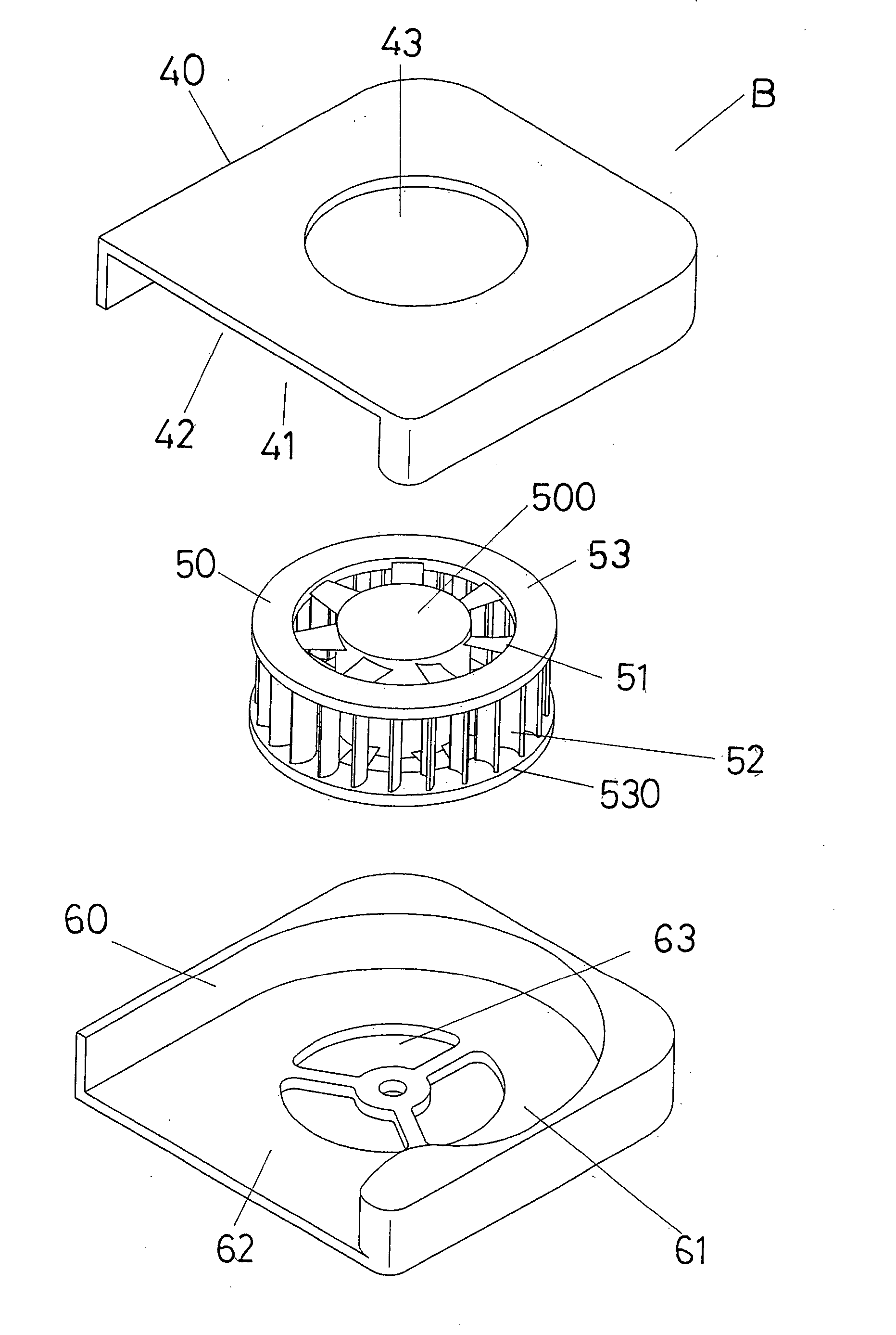
[0012] Referring to FIGS. 3 and 4, the fan device “B” of the present invention comprises a base 60 having a recess 61 defined in a first side thereof and three holes 63 are defined through a second side of the base 60. A first outlet 62 is defined in an end of the base 60.
[0013] A fan unit 50 is received in the recess 61 and includes a first ring 53 and a second ring 530 which is co-axially located at a distance from the first ring 53. A motor 500 is located at a center of the first and second rings 53, 530. A plurality of curve inner blades 51 extend from an inner periphery of the first ring 53 and are connected to the motor 500. A plurality of outer blades 52 extend from an underside of the first ring 53 and distal ends of the outer blades 52 are connected to the second ring 530.
[0014] A cover 40 has a recess 41 defined in an underside thereof and a hole 43 is defined through the cover 40. The cover 40 is connected to the base 60 and the fan unit 50 is located within the hole 43. A second outlet 42 defined in an end of the cover 40 and cooperated with the first outlet 62 of the base 60 to form a large outlet.
[0015] The two rings 53, 530 provide the fan unit 50 a strong structure and the fan unit 50 does not shake during operation. There is no limitation of the height for the inner and outer blades 51, 52 and air can be sucked from two sides of the fan unit 50 so that heat is removed by large volume.
[0016]FIGS. 5 and 6 show another embodiment of the fan device which includes a base 60′ having a recess 61′ defined in a first side thereof and an outlet 62′ is defined in an end of the base 60′. A fan unit 50′ is received in the recess 61′ and includes a first ring 53′ and a motor 500 is located at a center of the first ring 53′. A plurality of curve inner blades 51′ extend from an inner periphery of the first ring 53′ and are connected to the motor 500. A plurality of outer blades 52′ extend from an underside of the first ring 53′. A cover 40′ has a hole 43′ is defined therethrough and the cover 40′ is connected to the base 60′ and the fan unit 50′ is located within the hole 43′.
[0017] While we have shown and described the embodiment in accordance with the present invention, it should be clear to those skilled in the art that further embodiments may be made without departing from the scope of the present invention.

PUM

no PUM

Description & Claims & Application Information

We can also present the details of the Description, Claims and Application information to help users get a comprehensive understanding of the technical details of the patent, such as background art, summary of invention, brief description of drawings, description of embodiments, and other original content. On the other hand, users can also determine the specific scope of protection of the technology through the list of claims; as well as understand the changes in the life cycle of the technology with the presentation of the patent timeline. Login to view more.
Why Eureka
Try Eureka