Eureka AIR delivers breakthrough ideas for toughest innovation challenges, trusted by R&D personnel around the world.

Extruded tubing for mixing reagents

Inactive Publication Date: 2006-03-09
SCHRYVER CHARLES +1
View PDF23 Cites 32 Cited by
  • Summary
  • Abstract
  • Description
  • Claims
  • Application Information

AI Technical Summary

Benefits of technology

[0010] The present invention is directed to a mixing tube having unitary construction operable for receiving and mixing two or more fluids as they pass through the mixing tube that substantially obviates one or more of the limitations of the related art. To achieve this and other advantages, and in accordance with the purpose of the invention as embodied and broadly described herein, the invention includes a tube having a length and a lumen coextensive with the length. At least one, and preferably both, of the opposing end

Problems solved by technology

Prior art mixing devices lack “unitary” construction (i.e., such devices must be assembled from component parts).
Again, the device lacks unitary construction and the construction and operation of the device impose practical limitations on the length of the mixing path.
Articles having integral construction are generally rigid, are relatively costly to construct and may break at the joining interface.
It is, however, difficult to dispose baffle means within the lumen of a tube.
A mixing tube having baffles disposed in a lumen may be made by injection molding, but such mixing tubes are limited in length due to practical limitations on the size of a mold.

Method used


Image

  • Extruded tubing for mixing reagents
  • Extruded tubing for mixing reagents
  • Extruded tubing for mixing reagents

Examples


Embodiment Construction

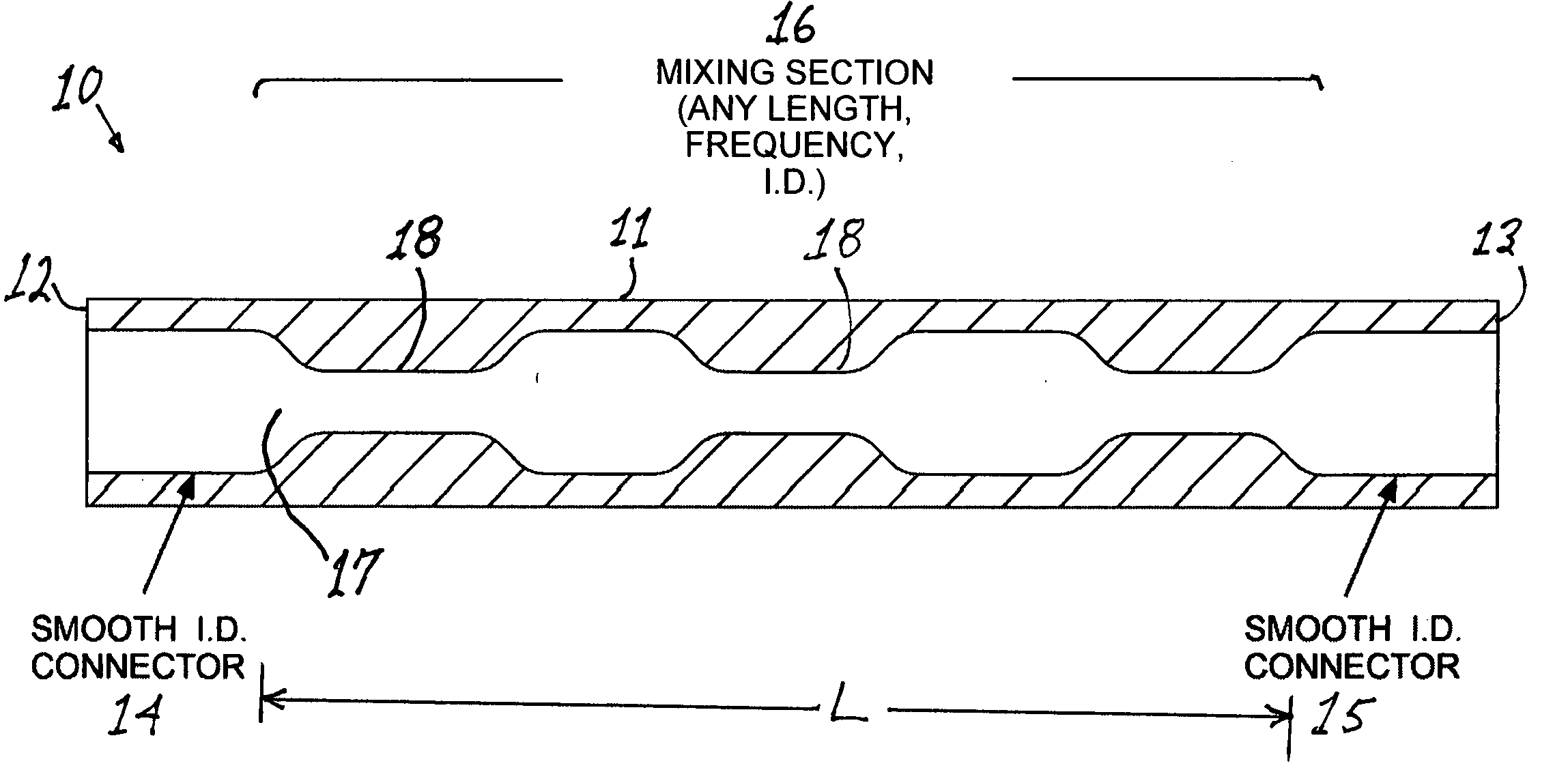
[0018] With reference now to FIG. 1, a mixing tube having a body 11, two opposing ends 12 and 13 and a lumen 17 is shown at numeral 10 in longitudinal cross-sectional view wherein the inner diameter of the mixing portion 16 varies sequentially and periodically along the length L of the mixing portion 16 to create a series of baffles 18 operable for creating turbulence in a fluid flowing through the lumen 17. The opposing ends 12 and 13 of the mixing tube 10 have a smooth cylindrical lumen 14 and 15 therewithin that are adapted to be attached to a standard tubing connector or a fluid-conducting manifold (not shown). In practice, two or more fluids are introduced simultaneously, and under pressure, into one end 12 or 13 of the mixing tube 10 as, for example, through a “tee” tubing connector. The velocity of the fluids through the narrow constricted portions of the mixing portion 16 of the lumen is higher than the velocity through the expanded portions (i.e., the portions of the lumen ...


PUM

PropertyMeasurementUnit
Lengthaaaaaaaaaa
Diameteraaaaaaaaaa
Flexibilityaaaaaaaaaa

Abstract

An extruded, preferably flexible mixing tube having unitary construction and a lumen coextensive with the length thereof. A mixing portion of the lumen is tortuous and operable for mixing two or more comingled fluids flowing therethrough. The lumen of the mixing tube preferably includes a smooth cylindrical connector portion at both ends thereof dimensioned to receive tubing connectors. The mixing portion of the lumen is disposed between the connector portions and is in fluid communication with the connector portions of the lumens at both ends of the mixing tube. The mixing tube may be extruded in any desired length. The tortuous mixing portion of the lumen may have any desired cross-sectional geometry. In one embodiment the mixing portion is defined by a spiral conduit. In another embodiment, the mixing portion of the lumen varies in internal diameter periodically along the length of the mixing tube. In yet another embodiment, the mixing portion is comprised of a linear sequence of two or more tortuous conduits having different cross-sectional geometries.

Description

REFERENCE TO RELATED APPLICATIONS [0001] Reference is made herein to copending U.S. patent application Ser. No. 10 / 778,366, filed Feb. 12, 2004 by the present inventor.BACKGROUND OF THE INVENTION [0002] 1. Field of the Invention [0003] The present invention relates to a fluid mixing tube and, more particularly, to an extruded tube having a lumen coextensive with the length thereof wherein the lumen includes a mixing portion. [0004] 2. Prior Art [0005] The problem of thoroughly mixing two or more fluids is well known in the art and has been addressed by artisans to produce various devices and methods. Prior art mixing devices lack “unitary” construction (i.e., such devices must be assembled from component parts). For example, Kojima, in U.S. Pat. No. 5,605,400, discloses a mixing element comprising a cylindrical pipe through which a liquid flows, and a plurality of blade bodies disposed within the pipe. The blade bodies form a plurality of fluid passages extending spirally and in a l...

Claims


Application Information

Patent Timeline
IPC IPC(8): B29C47/00B01F5/06B29C48/09
CPCB01F5/0646B01F5/0655B01F5/0656B29C47/0023B29C47/003B29L2031/7732B29C47/20B29C47/24B29C47/54B29L2023/00B29C47/0033B29C48/09B29C48/12B29C48/13B29C48/32B29C48/33B01F25/4338B01F25/434B01F25/433
Inventor SCHRYVER, CHARLESWAGES, MASON
Owner SCHRYVER CHARLES
Why Eureka
Eureka Blog
Learn More