Telemetry antennas for medical devices and medical devices including telemetry antennas

a technology of telemetry antennas and medical devices, applied in non-resonant long antennas, artificial respiration, therapy, etc., can solve the problem of limited portion of headers within which the antenna can be located, and achieve the effect of increasing volume, increasing antenna gain and antenna bandwidth

Active Publication Date: 2012-10-18
ST JUDE MEDICAL LUXEMBOURG HLDG SMI S A R L SJM LUX SMI
View PDF1 Cites 187 Cited by
  • Summary
  • Abstract
  • Description
  • Claims
  • Application Information

AI Technical Summary

Benefits of technology

[0022]In accordance with alternative embodiments, the three-dimensional shape of the antenna can be an elliptic cylinder, an oval cylinder, an elongated pentagonal prism, an elongated hexagonal prism, or another three-dimensional shape that could fit within the header and has a larger volume than a helical antenna having a right circular cylinder circumferential shape (that could fit within the header). For a given amount of available space within a header of a medical device, these alternative embodiments can also be used to provide greater antenna gain and antenna bandwidth than could be obtained using a helical antenna having a right circular cylinder circumferential shape that could fit within the header. This is in part because a volume occupied by the antenna having a circumferential shape of an elliptical cylinder, an oval cylinder, an elongated pentagonal prism or an elongated hexagonal prism is greater than a volume that could be occupied by a helical antenna having a right circular cylinder circumferential shape that could fit within the header.

Problems solved by technology

Since the connector(s) occupy a portion of the header, the portion of the header within which the antenna can be located is limited.

Method used


Image

  • Telemetry antennas for medical devices and medical devices including telemetry antennas
  • Telemetry antennas for medical devices and medical devices including telemetry antennas
  • Telemetry antennas for medical devices and medical devices including telemetry antennas

Examples


Embodiment Construction

[0040]The following description is of various embodiments of the present invention. The description is not to be taken in a limiting sense but is made merely for the purpose of describing the general principles of the invention. The scope of the invention should be ascertained with reference to the claims. In the description of the invention that follows, like numerals or reference designators will be used to refer to like parts or elements throughout. In addition, the first digit of a reference number identifies the drawing in which the reference number first appears.

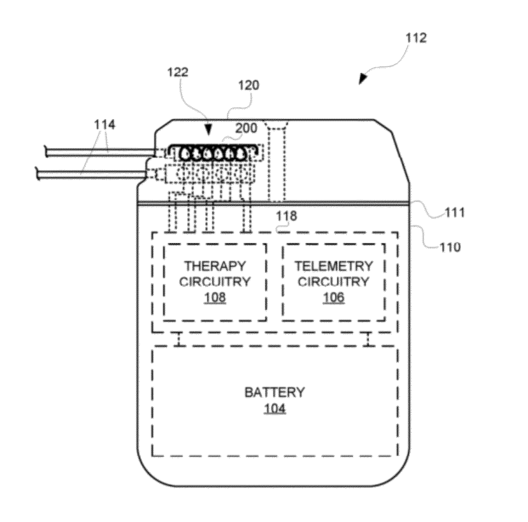
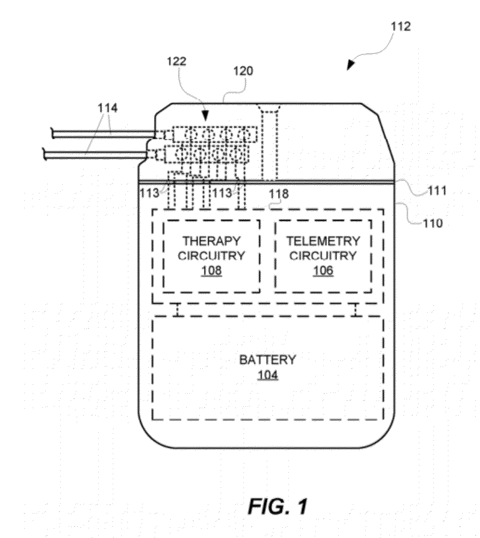
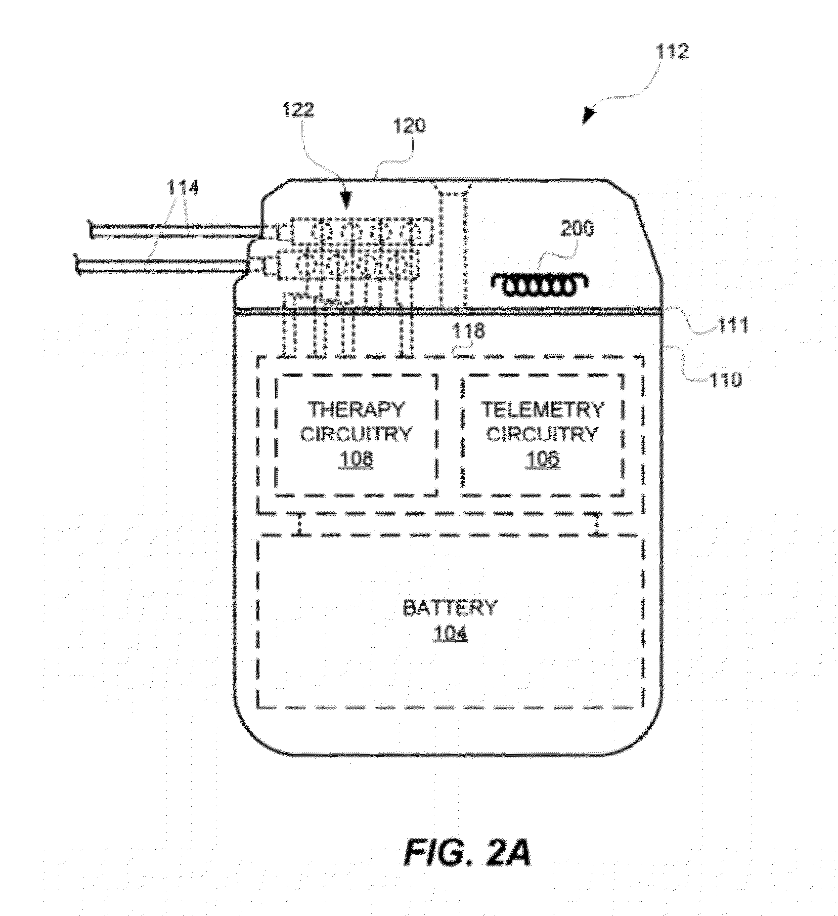
[0041]Exemplary dimensions of an IMD 112 are shown in FIGS. 3A-3C, with FIG. 3A illustrating a front view of the IMD, FIG. 3B illustrating a side view of the IMD, and FIG. 3C illustrating a top view of the IMD 112. The IMD includes a device housing 110 and a header 120. The device housing 110 can be made from a medical grade metal. The header 120 can be molded from a relatively hard, dielectric, non-conductive polymer ...


PUM


Abstract

In an embodiment, an antenna for a medical device, e.g., an implantable medical device (IMD), comprises an electrically conductive wire that spirals to form a three-dimensional shape of a rectangular cuboid. In another embodiment, the antenna comprises an electrically conductive wire that spirals to form a three-dimensional shape of an elliptical cylinder, an oval cylinder, an elongated pentagonal prism, an elongated hexagonal prism, or some other shape where the longitudinal diameter of the antenna is greater than the lateral diameter of the antenna. The antennas are sized to fit within a portion of a header of the medical device. Such antennas are designed to provide increased antenna gain and antenna bandwidth.

Description

PRIORITY CLAIM[0001]This application claims priority under 35 U.S.C. 119(e) to U.S. Provisional Patent Application No. 61 / 475,197, filed Apr. 13, 2011, (Attorney Docket No. SPMOD-01004US0), which is incorporated herein by reference.FIELD OF THE INVENTION[0002]Embodiments of the present invention generally relate to antennas for enabling medical devices to wireless communicate with base stations, medical devices including such antennas, and related methods, devices and systems.BACKGROUND OF THE INVENTION[0003]A medical device (MD) can be implanted in a patient for various different purposes, including, but not limited to, treating physiologic conditions, monitoring physiological conditions, treating neurological conditions, monitoring neurological conditions, diagnosing diseases, treating diseases, or restoring functions of organs or tissues. Where the MD is implanted, it is often referred to as an implantable medical device (IMD). Examples of IMDs include, but are not limited to, im...

Claims


Application Information

Patent Timeline
Patent Type & Authority Applications(United States)
IPC IPC(8): A61N1/36
CPCA61N1/37223H01Q11/08H01Q1/362H01Q1/273
Inventor JUDKINS, JAMES G.
Owner ST JUDE MEDICAL LUXEMBOURG HLDG SMI S A R L SJM LUX SMI
Why Eureka
Try Eureka