
Rack level power management for power over Ethernet

Inactive Publication Date: 2006-03-09
NEVERMORE SOLUTIONS
View PDF26 Cites 261 Cited by
  • Summary
  • Abstract
  • Description
  • Claims
  • Application Information

AI Technical Summary

Benefits of technology

[0015] In the event that sufficient power is available, ports of the next priority are then powered in a similar fashion. Thus all ports of a higher priority are enabled prior to enabling ports of a lower priority. Furthermore there is no requirement for confirmation that powering has been completed. The use of power budgets further allows for continued operation in the event of a communication failure.

Problems solved by technology

Over time, additional ports may require power, with a resultant need for additional sources of power.
A major difficulty in the use of a plurality of power sources is the action that must be taken in the event of a failure, or reduced output, of one of the plurality of power sources.
Furthermore, at start up or upon the addition of a power source to the plurality of power sources, a large number of ports may be potentially powerable.
In the event that a port has not been enabled, detection and optional classification may be accomplished however subsequent powering is not accomplished.
Furthermore, upon initial powering of a PD, an inrush current which is in excess of the normal operating current is typically observed.
One solution is to enable all the attached PoE devices, unfortunately this will result in a power demand exceeding total available power, resulting in early power supply failure or unreliable powering of at least one port.
This problem is further exacerbated by the inrush current.
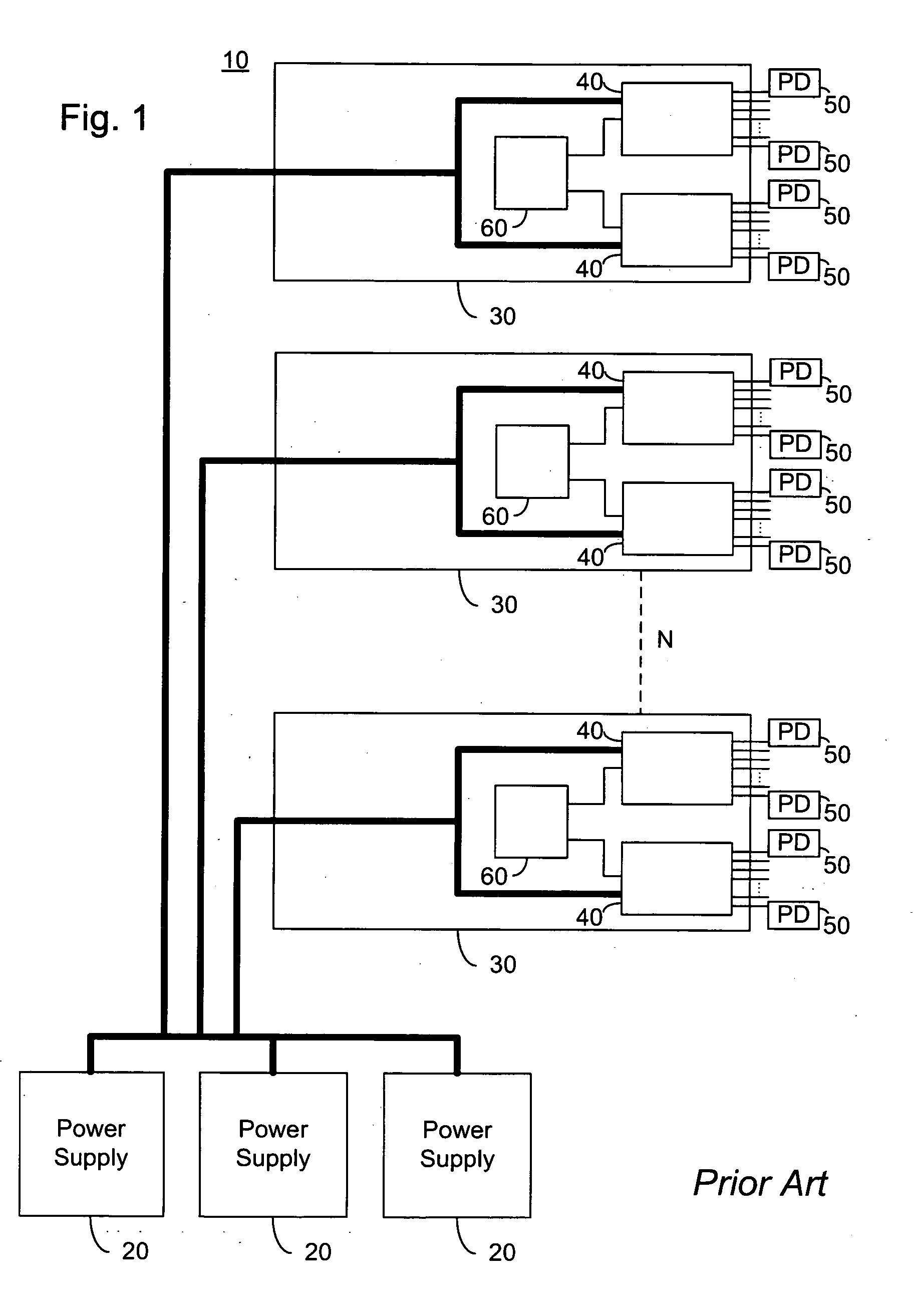
Furthermore, global priority is not maintained, as individual PoE devices may power according to priority, however priority across PoE devices is not adhered to.
This may result in low priority ports attached to a first PoE device being powered, while a high priority port attached to a second PoE device is not powered.
Unfortunately this is very time consuming, and for very large systems results in unacceptable delays.

Method used


Image

  • Rack level power management for power over Ethernet
  • Rack level power management for power over Ethernet
  • Rack level power management for power over Ethernet

Examples


Embodiment Construction

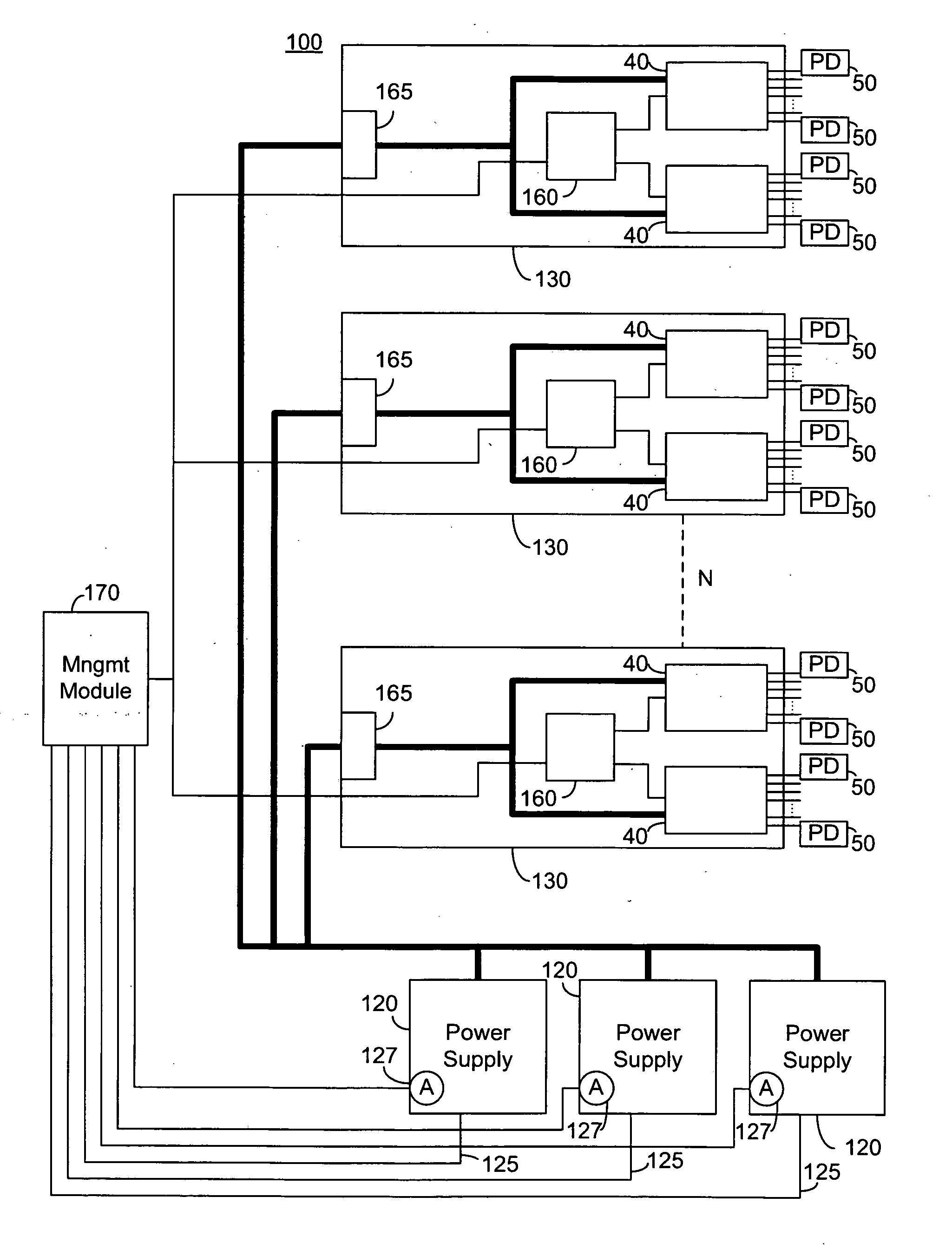
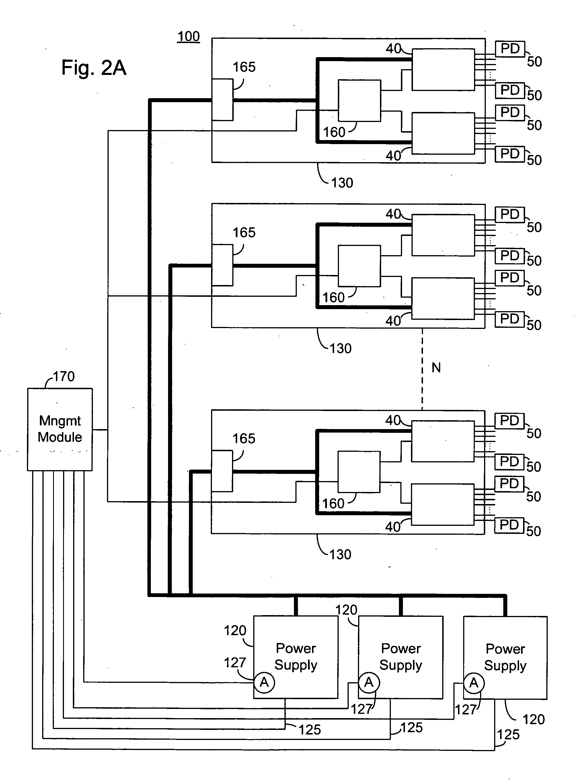
[0046] The present embodiments enable rapidly powering a large number of ports connected to disparate PoE devices, each of the PoE devices receiving power from a central power source. Preferably the central power source comprises a plurality of power supplies. This is provided by inputting an indication of available power, and allocating a power budget to each PoE device connected based on the input available power. Ports of a first priority are then enabled, with each PoE device powering ports of the first priority up to the allocated power budget. PoE devices which are unable to power ports of the first priority due to the limitation of the power budget subsequently receive an updated power budget until all ports of the first priority are powered.

[0047] According to an aspect of the invention power consumption is monitored after an enabling command is transmitted. Power consumption is monitored until stabilization indicative that all ports have been powered responsive to the enab...


PUM


Abstract

A method for rapidly powering a plurality of power over Ethernet ports, the method comprising: inputting an indication of available power; allocating a power budget to each of a first plurality of power over Ethernet devices; transmitting an enabling command for ports of a first priority to the first plurality of power over Ethernet devices, each of the first plurality of power over Ethernet devices powering ports of the first priority within the power budget; monitoring an indication of power consumption until the power consumption has stabilized; allocating an updated power budget to each of the first plurality of power over Ethernet devices, the power budget being a function of the available power and at least one of an indication of power consumption and power allocation; and transmitting an enabling command for ports of a second lower priority to the first plurality of power over Ethernet devices.

Description

CROSS-REFERENCE TO RELATED APPLICATIONS [0001] This application claims priority from U.S. Provisional Patent Applications Ser. No. 60 / 695,190 filed Jun. 30, 2005 entitled “Backplane Power Management” and Ser. No. 60 / 644,002 filed Jan. 18, 2005 entitled “System for Providing Power Over Ethernet Through a Patch Panel, and is a continuation in part of pending U.S. patent application Ser. No. 10 / 750,856 filed Jan. 5, 2004 entitled “Direct Current Power Pooling” which is a continuation of PCT Patent Application PCT / IL03 / 00832 filed Oct. 14, 2003 which claims priority from U.S. Provisional Patent Application Ser. No. 60 / 418,599 filed Oct. 15, 2002. This application is related to co-filed U.S. Patent Applications entitled “Rack Level Power Management” identified by docket number PDS-033-US; “Method for Detecting Parameter of a Remote Device” identified by docket number PDS-031-US; and “System for Providing Power Over Ethernet Through a Patch Panel” identified by docket number PDS-023-US. T...

Claims


Application Information

Patent Timeline
IPC IPC(8): G06F1/26
CPCH04L12/40045H04L12/10G06F1/26G06F1/30
Inventor GIAT, YANIVBLAUT, RONIFERENTZ, ALONPINCU, DAVID
Owner NEVERMORE SOLUTIONS
Learn More