
Method and apparatus for the production of energy

Active Publication Date: 2006-03-16
ADVANCED COMBUSTION ENERGY SYST
View PDF25 Cites 128 Cited by
  • Summary
  • Abstract
  • Description
  • Claims
  • Application Information

AI Technical Summary

Benefits of technology

[0111] In one aspect, the present invention provides processes and apparatuses for safely, rapidly, cost-effectively and efficiently producing and controlling high-energy, high purity superheated steam products or dry saturated steam products in an environmentally clean manner preferably using waste materials, such as the rubber from scrap tires, discarded carpet, used plastic soda bottles and / or Styrofoam coffee cups, or hazardous materials as a fuel. The resulting superheated steam products or dry saturated steam products can be employed to generate large quantities of electrical power without corroding or otherwise damaging turbines, condensers or other electrical power-producing equipment or devices.

Problems solved by technology

Further, the '212 patent does not teach or suggest the use of waste materials as a fuel.
It is likely that during this one combustion process, only an incomplete (partial) combustion of the fuel occurs, permitting environmental pollutants and / or hazardous materials to be present in the combustion gas exhaust product.
The patent does not teach or suggest an apparatus that does not have air enter into it, or come into contact with reactants used therein, or an apparatus that does not use air as an oxidizer.
Second, the apparatus described in the '038 patent only incinerates waste or hazardous materials that are fluidized or gaseous.
The patent does not teach or suggest an apparatus that can incinerate solid waste or hazardous materials.
Third, the waste and hazardous materials discussed in the '038 patent are not employed as a fuel.
The patent does not teach or suggest an apparatus that can use waste or hazardous materials as the fuel.
The patent does not teach or suggest the use of more than one combustion chamber or area, the production of more than one combustion reaction, or the production of any incomplete combustion reactions.
Fifth, the '038 patent does not teach or suggest the production of a superheated steam product or a dry saturated steam product.
The '071 patent does not teach or suggest the use of the polymer blend as a fuel, and does not discuss the generation of steam or power, or combustion gas generators.
Sixth, corrosion and other damage to turbines is typically caused by contact with unburned fuel particles and / or ash that are generally present in combustion gas products produced by the incomplete combustion of low grade fuels and / or solid fuels.
Eventually, such contact usually completely destroys the turbines.
First, the '264 patent does not teach or suggest the use of waste materials as fuel.
Second, the '264 patent does not teach or suggest a generator that does not permit air to enter into it.
Third, the '264 patent does not teach or suggest a generator that does not have water come into contact with combustion gases or combustion gas products produced therein.
Fourth, the '264 patent does not teach or suggest a generator that produces a combustion gas exhaust product that does not come into contact with a turbine or other electrical power-generating device.
Fifth, the '264 patent does not teach or suggest a generator that has more than one combustion chamber.
Sixth, the '264 patent does not teach or suggest the production of a superheated steam product or a dry saturated steam product, or the exiting of a superheated steam product or dry saturated steam product from the generator separately from combustion gas products produced by the generator.
If a solid fuel is used, and is not completely converted into a gas, it will have a detrimental effect on the blades of the turbine.

Method used


Image

  • Method and apparatus for the production of energy
  • Method and apparatus for the production of energy
  • Method and apparatus for the production of energy

Examples


example 1

Hydrocarbon Combustion Gas Generator

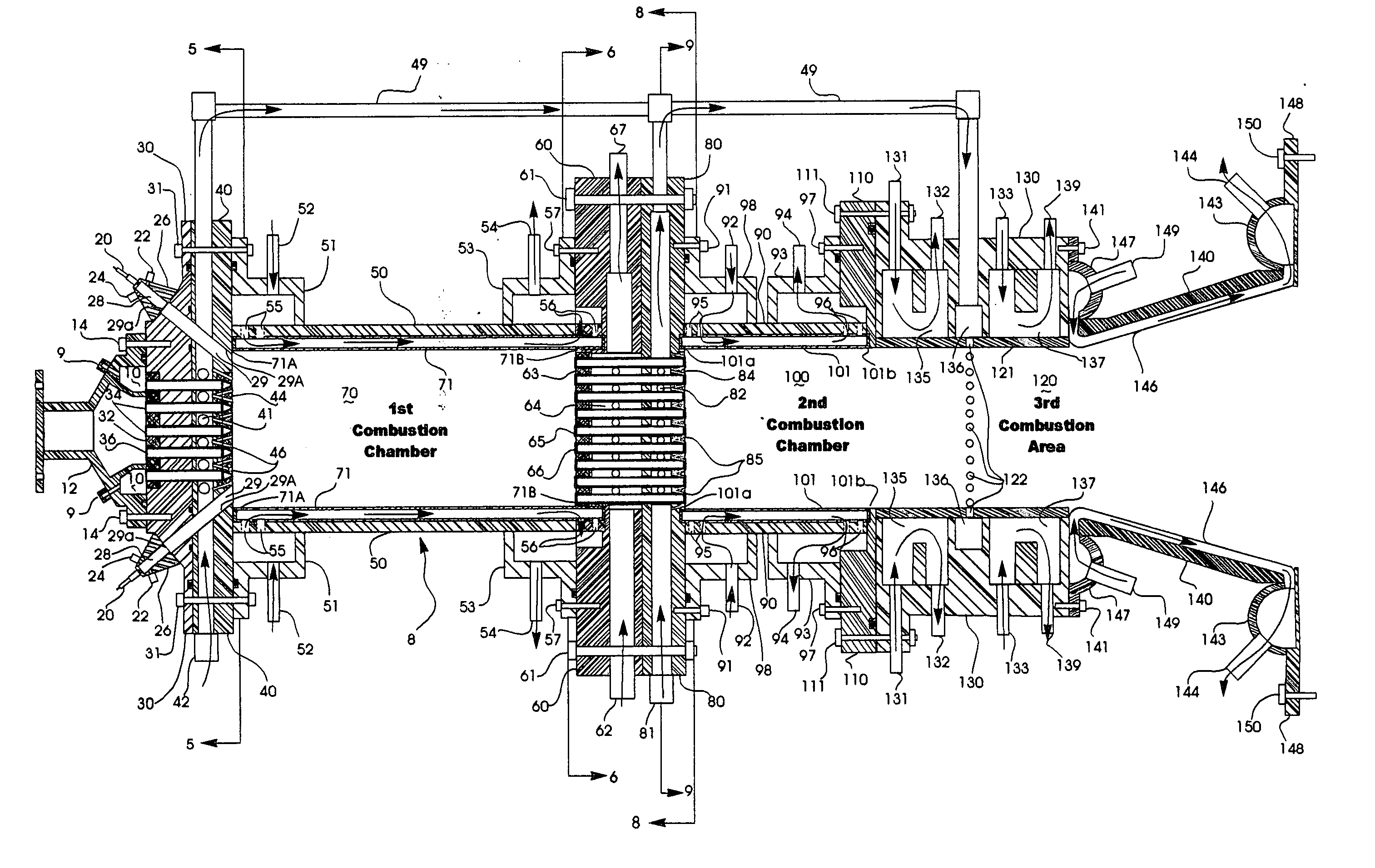
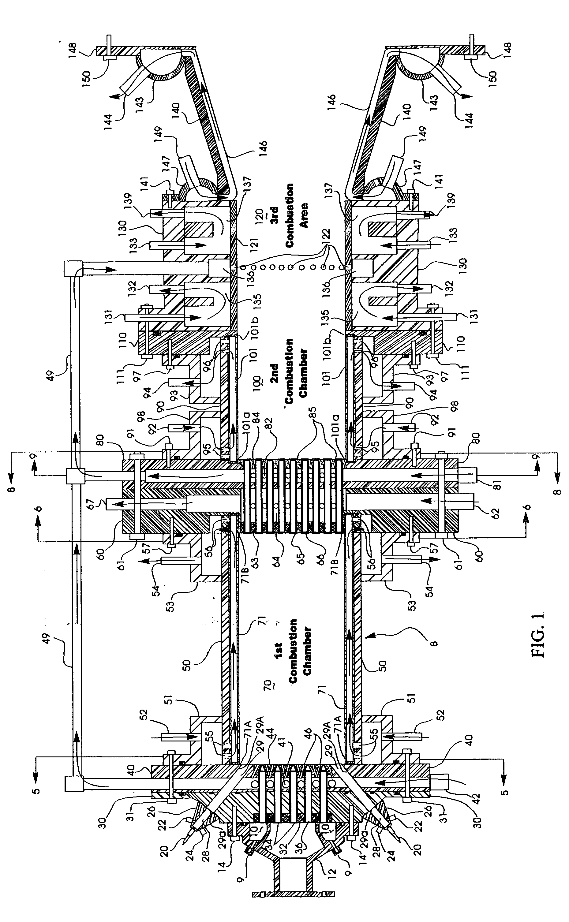
[0739] In this example, a 10-megawatt hydrocarbon combustion gas generator (“generator”) having about a 97% combustion efficiency is constructed of austenitic / ferritic steel generally in the manner shown in the drawings. The generator has an overall length of about 162 inches and an overall outside diameter of about 16.75 inches. It has two combustion chambers and a third combustion area, each of which has an inside diameter of about 13.25 inches and an outside diameter of about 14.75 inches. However, the portion of the third combustion area from which a combustion gas exhaust product exits the generator has different diameters. This part of the third combustion area is cone shaped, with the forward end of the cone having an inside diameter of about 13.25 inches and an outside diameter of about 14.75 inches, and with the aft end of the cone having an inside diameter of about 25 inches and an outside diameter of about 26.50 inches.

[0740] The firs...

example 2

Analysis of Components of Combustion Gas Exhaust Products After Natural Gas, Methanol and Kerosene are Separately Combusted in a 10-Megawatt Hydrocarbon Combustion Gas Generator of the Invention Using Air or LOX as the Oxidizer

[0753] The components, quantities thereof (in terms of number of moles and pounds) and weight percents thereof that are present in the combustion gas exhaust products produced after 2,000 pounds (1 ton) of natural gas, methanol and kerosene (oil #1) are separately combusted in the 10-megawatt hydrocarbon combustion gas generator described in Example 1, using either air or LOX as the oxidizer, with each combustion gas exhaust product exiting the hydrocarbon combustion gas generator at a pressure of about 1,000 psig and at the indicated temperature (which varies at 1,000 psig, depending upon the type of fuel and oxidizer employed), were determined using the thermochemical computer software GUIPEP, and are set forth in the tables below. (In contrast with the app...

example 3

Analysis of Components of Combustion Gas Exhaust Products After Eighteen Different Engineered Fuels are Separately Combusted in a 10-Megawatt Hydrocarbon Combustion Gas Generator of the Invention

[0760] The components, quantities thereof (in terms of number of moles and pounds) and weight percents thereof that are present in the combustion gas exhaust products produced after 2,000 pounds (1 ton) of the eighteen Engineered Fuels described below are separately combusted in the 10-megawatt hydrocarbon combustion gas generator described in Example 1, using LOX as the oxidizer, with each combustion gas exhaust product exiting the hydrocarbon combustion gas generator at a pressure of about 600 psig and at the indicated temperature (which varies at 600 psig, depending upon the type of fuel employed), were determined using the thermochemical computer software GUIPEP, and are set forth in the tables below.

A. EF-1 Fuel (Exhaust Temperature of 2787° F.)Moles Present inPounds PresentCombustio...


PUM


Abstract

The invention provides processes and apparatuses for safely, rapidly, cost-effectively and efficiently producing a superheated steam product or dry saturated steam product that can be employed to generate electrical power, or in other manufacturing and / or non-manufacturing processes, in an environmentally clean manner without causing corrosion to electrical power-generating devices. These processes and apparatuses involve the combustion of one or more fuels containing the elements hydrogen and / or carbon, which can be derived from waste materials, such as the rubber from scrap tires. Water that circulates around one or more combustion chambers and / or areas, but that does not enter into the combustion chambers or areas, becomes converted into a high purity steam product The present invention also provides processes and apparatuses for recycling or eliminating waste materials, and for transforming hazardous materials into non-hazardous materials, and fuels that can be employed in the foregoing processes and apparatuses.

Description

BACKGROUND OF THE INVENTION [0001] 1. Field of Invention [0002] The present invention generally relates to processes and apparatuses that can convert waste materials, such as the rubber from scrap tires, discarded carpeting and used milk, water or soda bottles, into a high-purity, high-efficiency, high-energy, environmentally clean superheated steam product or dry saturated steam product in an efficient, cost-effective manner, while also beneficially extending the lifespans of landfills in which the waste materials would likely otherwise have been placed. [0003] Using an oxidizer other than air, the processes and apparatuses of the present invention convert chemical energy that is present in a fuel containing the element hydrogen, the element carbon or the elements hydrogen and carbon, which may be derived from waste materials, into thermal energy, which is transferred to surrounding water, converting the water into a superheated steam product or dry saturated steam product that can...

Claims


Application Information

Patent Timeline
IPC IPC(8): F01K13/00F23G5/00F23G5/027F23G5/16F23G7/00F23G7/12F23L7/00F23M5/08
CPCF23G5/006F23G2900/7011F23G5/16F23G7/003F23G7/12F23G2202/101F23G2202/103F23G2206/203F23G2209/20F23G2209/28F23L7/00F23L2900/07004F23L2900/07005F23M5/08Y02E20/12Y02E20/14Y02E20/344F23G5/027F28F21/083Y02E20/34
Inventor PRENTICE, JAMES ANDREW III
Owner ADVANCED COMBUSTION ENERGY SYST
Learn More