

Method and device for controlling an internal combustion engine
a technology of internal combustion engine and control device, which is applied in the direction of combustion engine, electric control, machines/engines, etc., can solve the problems of considerable effort in the reciprocal dependence of the conversion, and achieve the effect of reducing the complexity of the application
- Summary
- Abstract
- Description
- Claims
- Application Information
AI Technical Summary
Benefits of technology
Problems solved by technology
Method used
Image

Examples
Embodiment Construction
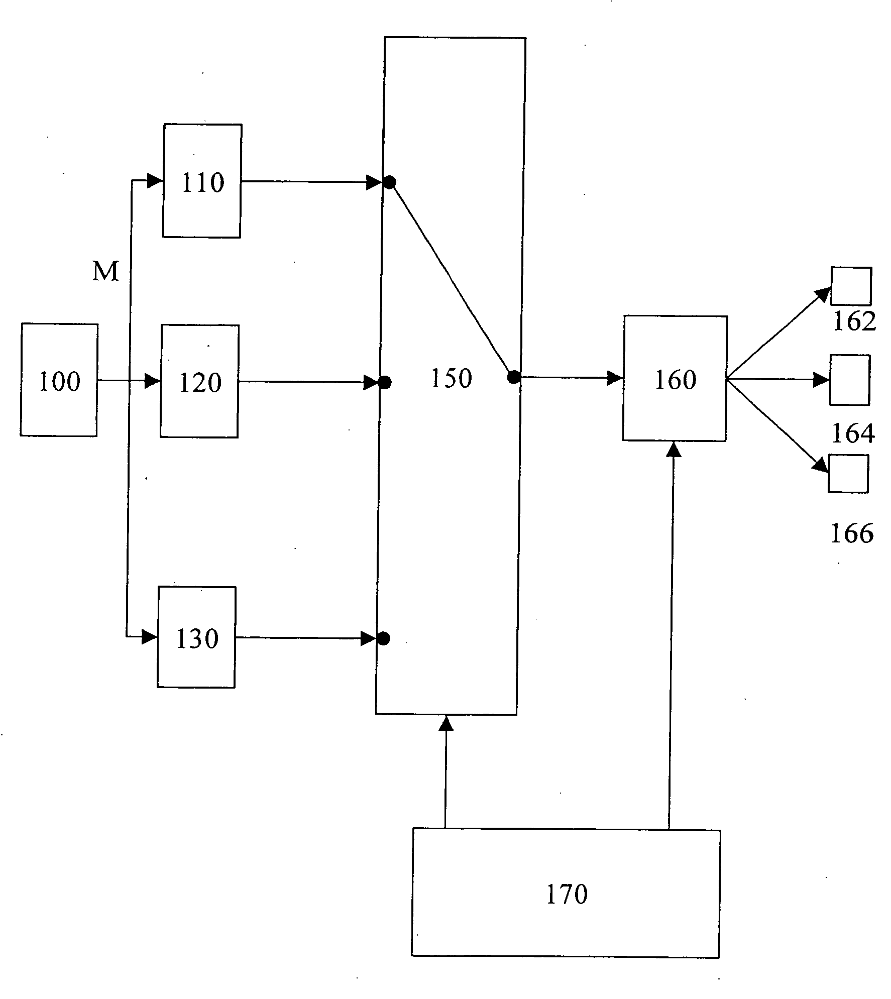
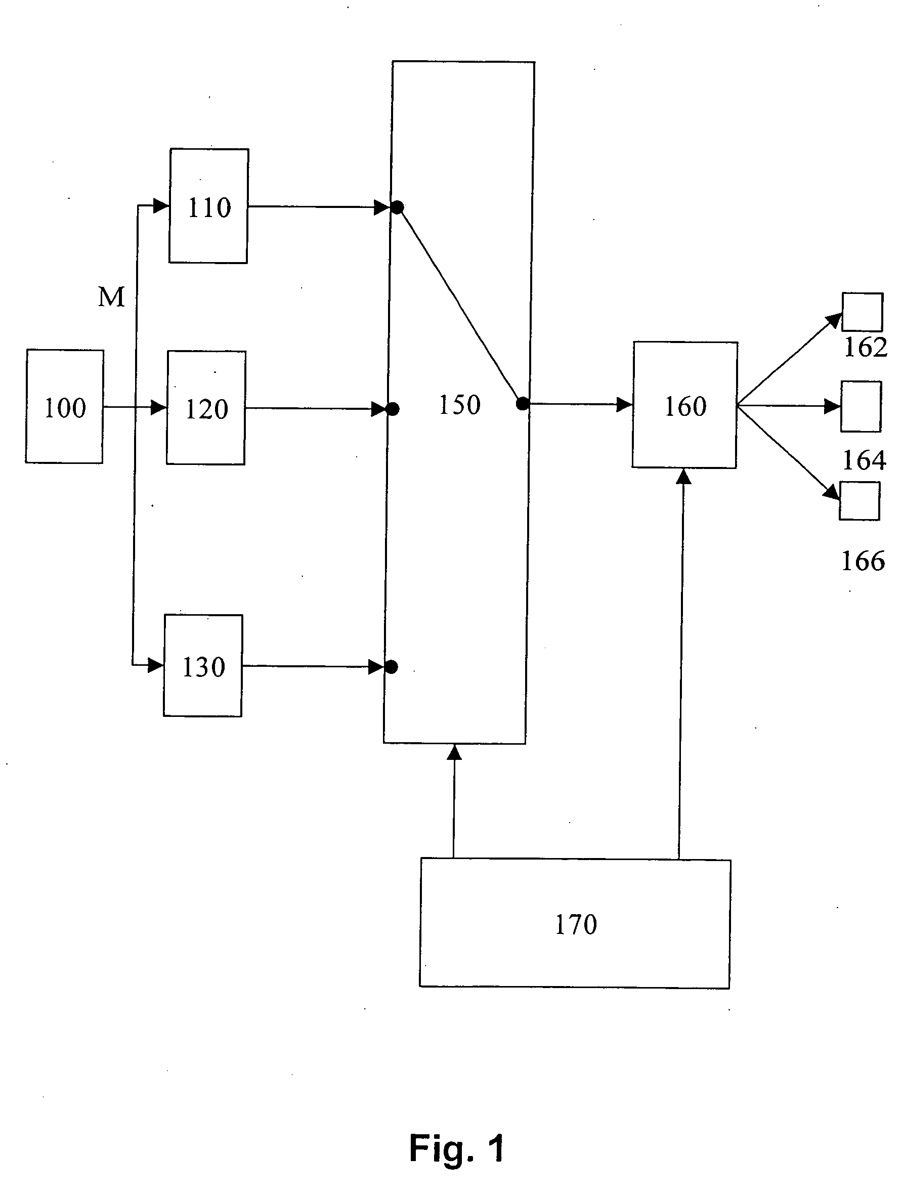
[0006] In FIG. 1, the procedure of the present invention is described using as an example an internal combustion engine having self-ignition. The procedure according to the present invention is not restricted to such an internal combustion engine. It may be used in a wide variety of internal combustion engines where a fuel quantity to be injected must be predefined on the basis of the desired torque. This specifically applies to all directly-injecting internal combustion engines and to internal combustion engines having self-ignition.
[0007] A torque setpoint selection is denoted by 100 in FIG. 1. It applies a signal M regarding the desired torque to a first procedure 110. Analogously, the corresponding second signal acts on a second setpoint selection 120. Signal M concerning the desired torque is applied to a third setpoint selection 130 as well. Three procedures 110, 120 and 130 are shown in FIG. 1. The procedure according to the present invention is not limited to this number of...
PUM
 Abstract
Description
Claims
Application Information