Apparatus for guiding and steering an earth boring machine and casing assembly

Inactive Publication Date: 2006-03-16
VELCOVER DAVID
View PDF4 Cites 6 Cited by
  • Summary
  • Abstract
  • Description
  • Claims
  • Application Information

AI Technical Summary

Benefits of technology

[0006] Accordingly, a primary objective of the device of the present invention is to provide a new, useful and heretofore unobvious steering head mechanism that can be used with an earth boring machine such that the earth boring machine can be periodically reversed without causing the steering head mechanism to seize during operation. A second objective is to provide such

Problems solved by technology

In the experience of this inventor, one difficulty encountered with the utilization of a steering head as described above is that a reversal of the steering head during the boring process tends to deposit earth into the drive mechanism, which is a threaded screw mechanism.
The presence of earthen debris about the drive mechanism can cause the mechanism to seize when the boring head is re-acti

Method used


Image

  • Apparatus for guiding and steering an earth boring machine and casing assembly
  • Apparatus for guiding and steering an earth boring machine and casing assembly
  • Apparatus for guiding and steering an earth boring machine and casing assembly

Examples


Example

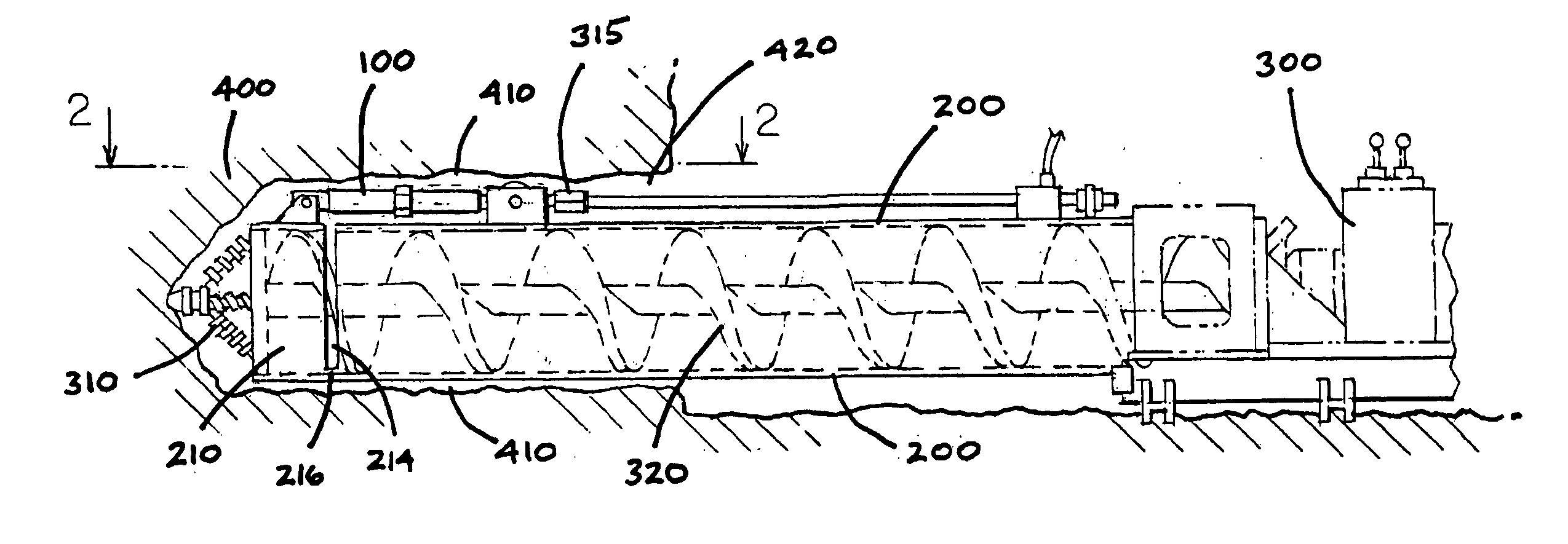
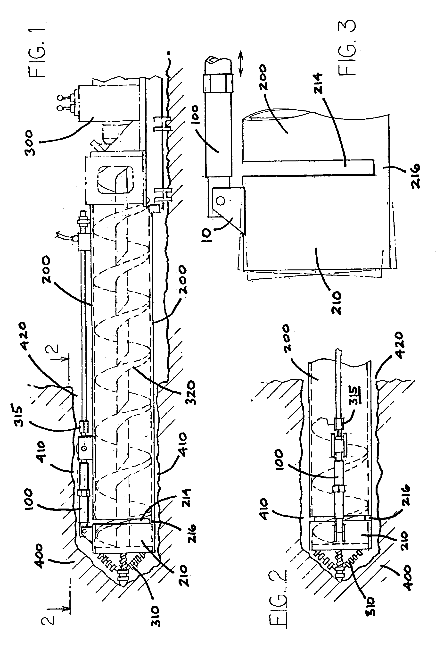
[0017] Referring now to the drawings in detail, wherein like numbered elements refer to like elements throughout, FIGS. 1 and 2 illustrate a steering head mechanism, generally identified 100, constructed in accordance with the present invention. As shown, the steering head mechanism 100 is utilized with a boring machine 300 and its related components that are used for cutting a bore 410 into the earth 400.

[0018] More specifically, it will be seen that the steering head mechanism 100 is attached to the foremost portion 210 of a longitudinally extending casing 200. The casing 200 is an elongate hollow pipe casing of conventional type and length that projects into the bore 410 within the earth 400. Forward of the casing 200 is an auger bore head 310. An auger 320 is rotated within the casing 200 to move debris through the casing 200 as it is loosened by the bore head 310. The auger 320 and bore head 310 are rotatably driven by the boring machine 300 which is located at the opening 420...


PUM


Abstract

A steering head that comprises a forward pivot block and a rearward pivot block. The forward pivot block is attached to a leading edge of a casing. The rearward pivot block is attached to a trailing portion of the casing, the leading edge being separated from the trailing portion by a gap in the casing. Extending between the forward and rearward pivot blocks is a central drive shaft. The central drive shaft includes a threaded portion and is rotatable to move a drive nut away from or towards the rearward pivot block. The central drive shaft, to either side of the drive nut, is covered by a cylindrical sleeve. A second internal sleeve extends between the rearward pivot block and the drive nut to protect the threads of the drive shaft from earthen debris when the casing is being advanced or reversed to steer the forward-most casing portion during operation.

Description

FIELD OF THE INVENTION [0001] The present invention relates generally to earth boring machines that are used to bore a substantially horizontal, and longitudinally extending, hole through the earth. It also relates generally to such machines where sections of pipe casing are concomitantly pushed into the horizontal hole to create a continuous casing within the bore. More particularly, it relates to an improved apparatus for guiding and steering a forward-most section of a pipe casing such that the hole and pipe direction are controlled during the boring process, which apparatus is resistant to seizing due to the presence of earthen debris that surrounds the apparatus. BACKGROUND OF THE INVENTION [0002] Earth boring machines that are used to create a horizontal bore, the bore being lined with a pipe casing, are well known in the art. Earth boring machines of this type typically utilize an auger at the forward, or leading, end of the pipe casing. The auger is rotated, thereby boring a...

Claims


Application Information

Patent Timeline
IPC IPC(8): E21B7/20
CPCE21B7/201E21B7/062
Inventor VELCOVER, DAVID
Owner VELCOVER DAVID
Why Eureka
Try Eureka