Two part oil or fluid drain plug with magnet

a technology of oil or fluid drain plugs and magnets, applied in the direction of crankshafts, machines/engines, magnetic separation, etc., can solve the problems of difficult to reach or see, and achieve the effect of difficult installation

Active Publication Date: 2006-03-16
DORIAN GEORGE P
View PDF21 Cites 46 Cited by
  • Summary
  • Abstract
  • Description
  • Claims
  • Application Information

AI Technical Summary

Benefits of technology

[0055] It is another object of the invention to provide a two part sump drain plug wherein the problem of engaging drain plug threads is solved in the following way: It is often inconvenient and difficult for one to reach the drain port of an oil sump 3, and this is often a cause of crossing drain plug threads 30. The reader may wish to refer to FIG. 4. My invention has a self aligning feature to aid the mechanic in inserting the plug 2 into the fitting 1. This feature is composed of a long nose 16 on the plug 2 and a non-threaded area 15 just in front of the plug's external threads 11. As the plug is inserted into the fitting, the nose 16 of the plug enters the internal threaded bore 10 of the fitting. This internal threaded part of the fitting is relatively large in diameter, so this makes an easy target area for the mechanic to locate the plug to the fitting. As the plug is further inserted into the fitting the nose of the plug enters the smaller smooth bore area 18 of the fitting. At the same time the non-threaded area 15 just in front of the plug's threads are centered within the first internal treads 17 of the fitting. So there is a two point alignment, at the front of the plug and to the rear of the plug. As the plug is inserted even further the threads 11 of the plug and threads 10 of the fitting start to engage. By this time the threads of the plug and fitting should be aligned such that they will not cross. It is notable that a number of test subjects have easily and consistently inserted prototypes of the plug of my invention into the fitting and screwed the two together—with their eyes closed. This is not a trivial matter, as many sump ports are difficult to reach or see from under a car.
[0056] It is another object of the invention to provide a two part sump drain plug wherein the invention incorporates a magnet 19, made of a rare earth Neodymium magnet, to draw out metal fragments 20 that may be borne in oil 12. The reader may wish to refer to FIG. 5. In many transmissions and most all differentials there is no oil filter, so a magnetic oil plug is used i...

Problems solved by technology

This is not a trivial matter, as many sump po...

Method used


Image

  • Two part oil or fluid drain plug with magnet
  • Two part oil or fluid drain plug with magnet
  • Two part oil or fluid drain plug with magnet

Examples


Embodiment Construction

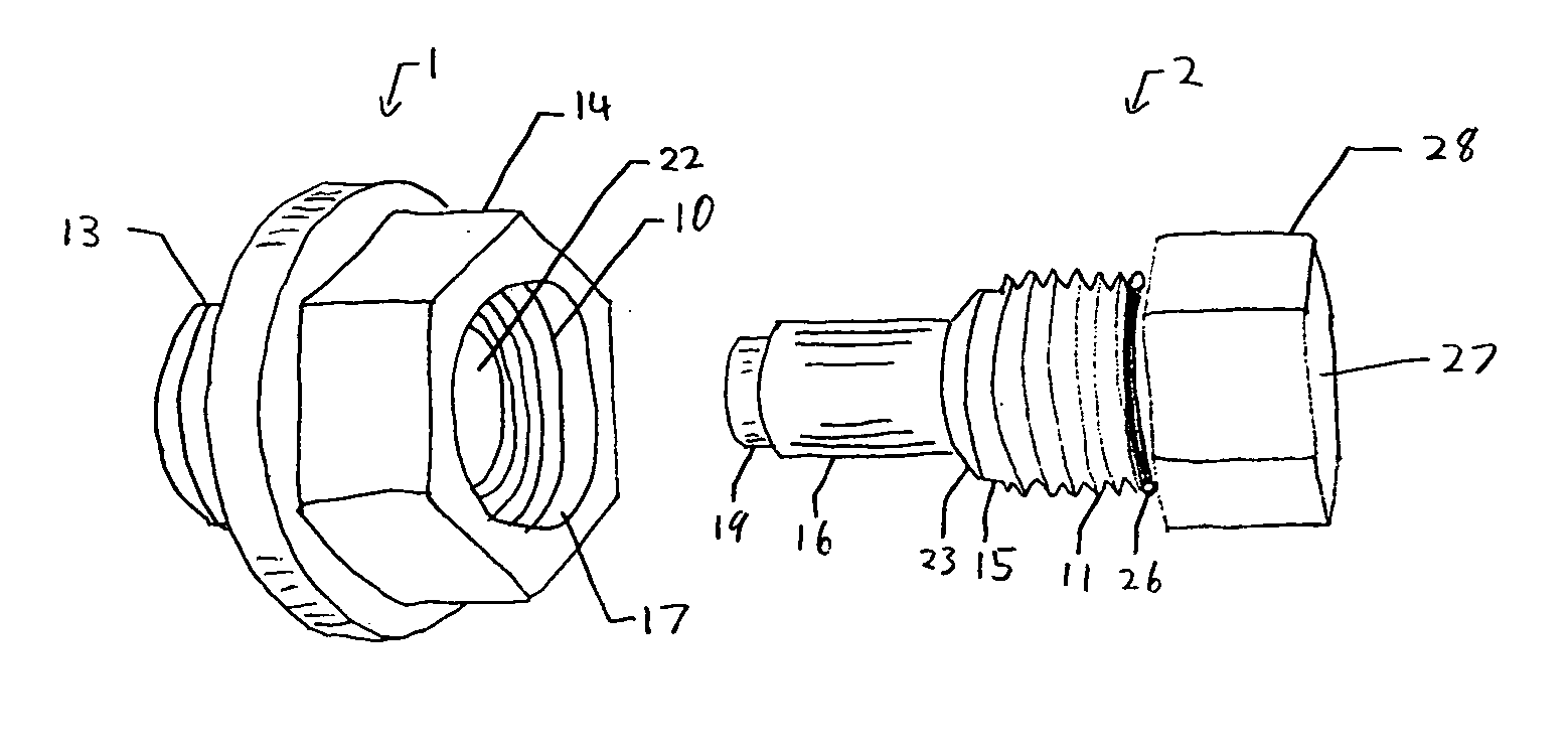
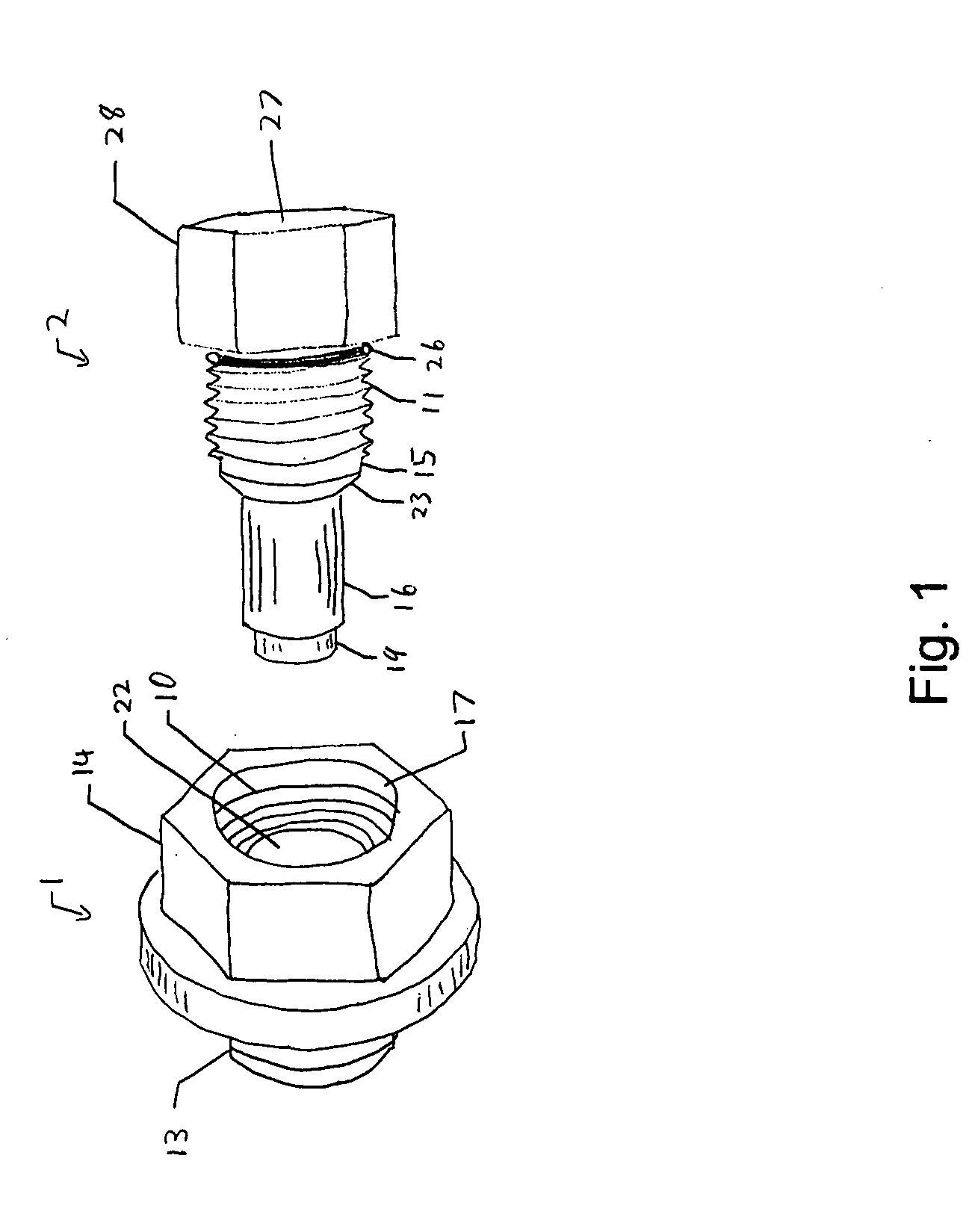
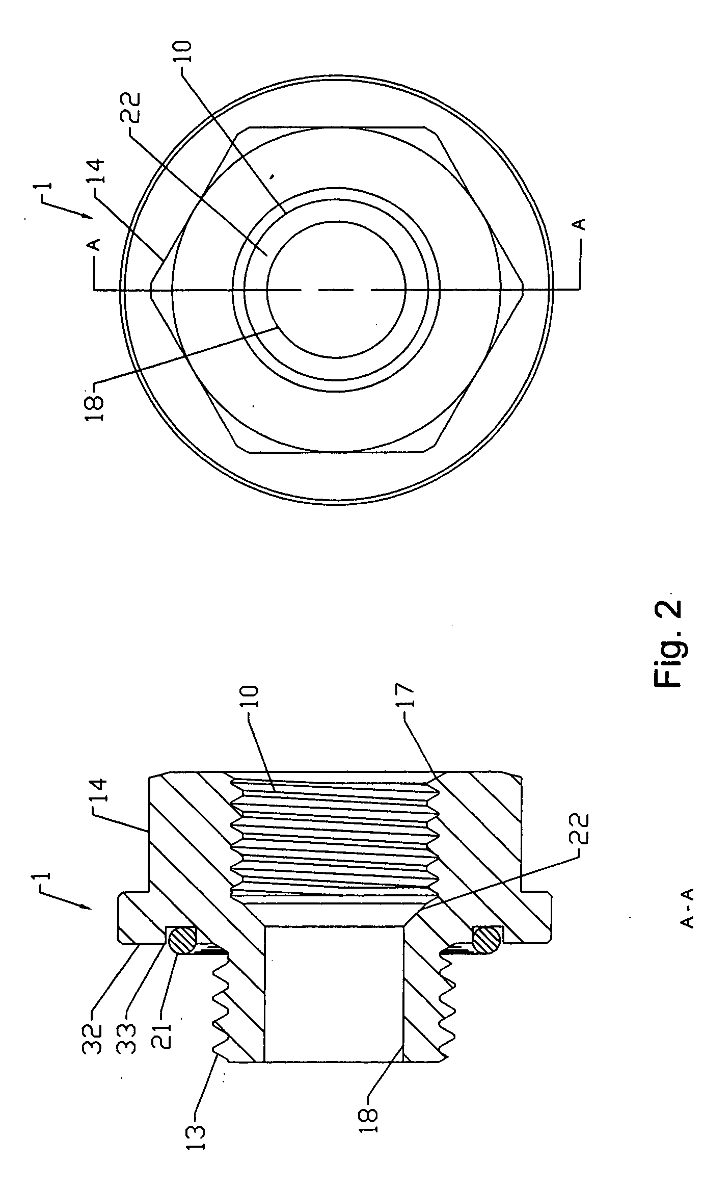
[0070] My invention is a two part drain plug which I developed in light of, and to solve, the numerous issues and problems described in the above section entitled Description of Prior Art. I feel that my invention is the best practical way to solve those problems of any that I've seen in my research.

LIST OF REFERENCE NUMERALS

[0071]1—The fitting body. [0072]2—The plug body. [0073]3—The sump. [0074]10—The internal threads of the fitting body. [0075]11—The external threads of the plug body. [0076]12—Oil. [0077]13—The external threads of the fitting body. [0078]14—The wrench flats of the fitting body. [0079]15—The non-threaded area before the external threads of the plug body. [0080]16—The nose of the plug body. [0081]17—The first internal thread of the fitting body. [0082]18—The smooth bore of the fitting body. [0083]19—The magnet. (non-tapered) [0084]20—Metal fragments. [0085]21—The O-ring of the fitting body. [0086]22—The conical shape of the fitting body. [0087]23—The conical shap...


PUM


Abstract

This invention performs several functions. First; facilitating the draining of oil or fluid from a sump. Second; as a proactive and preventive method of preventing the threads of the sump (which receive the drain plug) from becoming striped or damaged. Third; adding in the determination of the physical condition (ware) of the engine, transmission, or the like, in which the sump is attached to.

Description

BACKGROUND OF THE INVENTION [0001] 1. Field of the Invention [0002] This invention relates to oil and fluid drain plugs specifically to such two part magnetic drain plugs installed in an oil sump, and as a preventative measure to prevent the threads of the sump from damage, and as a diagnostic tool to determine wear of the engine, transmission, differential housing or machine by collecting small metal fragments that may be borne in the oil or fluid. [0003] 2. Description of Prior Art [0004] It is commonalty known that to replace oil in an internal combustion engine one must first remove the old oil. This is traditionally accomplished by unscrewing a drain plug from a sump (which includes a threaded hole for the drain plug) and letting the old oil drain into an appropriate receptacle. In general the sump is located at the lower part of the engine. After the old oil has drained the drain plug is screwed back into the sump, tightened, and new oil is added to the engine. [0005] Whether ...

Claims


Application Information

Patent Timeline
IPC IPC(8): F16N33/00
CPCF01M11/0408B03C1/286B03C2201/30
Inventor DORIAN, GEORGE P.
Owner DORIAN GEORGE P
Why Eureka
Try Eureka