Oil supplying structure of transmission for vehicle

a technology of oil supply structure and transmission, which is applied in the direction of gear lubrication/cooling, belt/chain/gearing, gear lubrication, etc., can solve the problems of reducing the amount of oil captured and becoming difficult to supply oil to the needle roller bearing, so as to achieve the effect of heightened oil separation performance of the breather chamber

Inactive Publication Date: 2006-03-16
KAWASAKI HEAVY IND LTD
View PDF19 Cites 10 Cited by
  • Summary
  • Abstract
  • Description
  • Claims
  • Application Information

AI Technical Summary

Benefits of technology

[0024] According to this mechanism, since the breather passage formed in the bottom wall is constituted to have a labyrinth structure, the performance of oil separation of the breather chamber is heightened. Further, since the breather passages of the bottom wall are constituted by notches which are formed on the pair of right and left case members in the location of the mating face, the breather passages which are offset from each other in the direction of width, can be made easily.

Problems solved by technology

As a result, the amount of oil captured decreases, and it may become difficult to supply oil to the needle roller bearings 310, 311 fully.

Method used


Image

  • Oil supplying structure of transmission for vehicle
  • Oil supplying structure of transmission for vehicle
  • Oil supplying structure of transmission for vehicle

Examples


Embodiment Construction

[0045] Before a description of the preferred embodiment of the present invention proceeds, it is to be noted that like or corresponding parts are designated by like reference numerals throughout the accompanying drawings.

[0046] Referring to FIGS. 1 through 18, the description is made below upon a four-wheel drive utility vehicle for transport of articles to which an oil supplying structure of a transmission according to a preferred embodiment of the present invention applies.

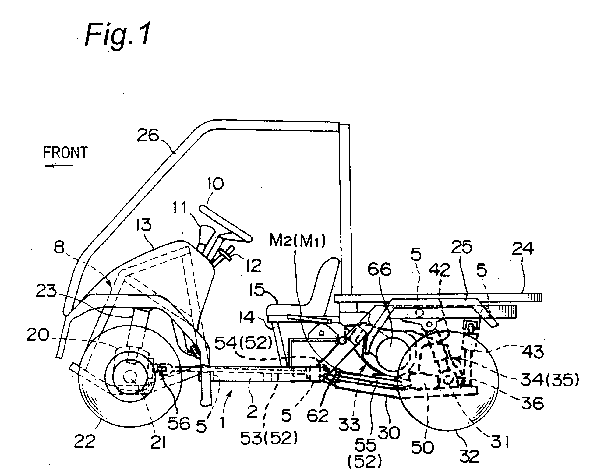
[0047] Namely, FIG. 1 shows a left side of the four-wheel drive vehicle, with respect to a direction in which the vehicle moves forward (hereinafter, referred to as “forward direction”). A body frame (i.e. vehicle body) 1 has a pair of right and left main pipes 2 formed with cornered pipes, each of which extends in a direction of the front and rear of the body frame 1 (hereinafter, referred to as “back-and-forth direction”), as main frames. The pair of right and left main pipes 2 are integrally fixed to each o...


PUM


Abstract

Disclosed is a structure which is able to supply oil to engagement parts of transmission gears mutually rotatably mounted on a transmission shaft inside a transmission case for a vehicle, even when the vehicle tilts during its run. The transmission shaft in the transmission case, has an oil passage which penetrates through its length axially and communicates with the engagement parts of the transmission gears fluidically, where the transmission shaft extends in a direction of width of the vehicle. Both ends of the oil passage of the transmission shaft fluidically communicate with oil intake passages which extend upwards and open inside the transmission case so as to capture the oil inside the transmission case.

Description

BACKGROUND OF THE INVENTION [0001] 1. Field of the Invention [0002] The present invention generally relates to an oil supplying structure of a transmission for a vehicle, and particularly relates to the oil supplying structure of the transmission for a four-wheel vehicle which is suitable for traveling on rough road, such as an all-terrain vehicle, a utility vehicle for transport of articles, and so on. [0003] 2. Description of the Related Art [0004]FIG. 19 is a view showing an example of a transmission of a conventional utility vehicle. That is, there are arranged an input shaft 301, an output shaft 302, and a reverse idle shaft 303, all as shafts for the transmission, inside a transmission case 300, where the three shafts 301, 302, 303 are positioned in parallel with each other and extend in a direction of width of the vehicle (hereinafter, referred to as “width direction”) In the construction, there is arranged a rear reduction gear case 306, where the case 306 locates on the rea...

Claims


Application Information

Patent Timeline
Patent Type & Authority Applications(United States)
IPC IPC(8): F16H57/04F16H57/02F16H57/027F16H57/031
CPCF16H57/027F16H57/0421F16H57/0494F16H57/0443F16H57/043
Inventor MIYAZAKI, TAKESHIKAMITAKE, MIKIONISHIMURA, SHIGERU
Owner KAWASAKI HEAVY IND LTD
Why Eureka
Try Eureka