Stator of motor

a technology of stators and motors, applied in the field of motors, can solve the problems of a motor including the conventional stator in fig. 3's efficiency becoming remarkably worse than that of a motor including the conventional stator in fig. 1 and 2's efficiency, and achieve the effect of proper efficiency and minimal manufacturing costs

Active Publication Date: 2006-03-16
LG ELECTRONICS INC
View PDF26 Cites 29 Cited by
  • Summary
  • Abstract
  • Description
  • Claims
  • Application Information

AI Technical Summary

Benefits of technology

[0016] Therefore, the present invention has been made in view of the above and / or other problems, and it is an object of the present invention to provide a stator of a motor of which some parts of the stator are manufactured according to the iron powder metallurgy method so as to reduce costs, to minimize core loss, and to enhance the efficiency of a motor due to the overhang effect.
[0031] According to the stator of a motor in accordance with the present invention, at least the teeth are manufactured by the iron metallurgy method so as to minimize the manufacturing costs. In order to obtain the overhang effect, the height of the tip of each tooth is lower than the height of the rotor and the height of the yoke is higher than the height of the tip of each tooth, so that the proper efficiency of a motor can be obtained.

Problems solved by technology

However, since the magnetic characteristics of the iron powder is not better than that of the electrical steel sheet, the efficiency of a motor including the conventional stator in FIG. 3 becomes remarkably worse than that of a motor including the stator 10 in FIGS. 1 and 2.

Method used


Image

  • Stator of motor
  • Stator of motor
  • Stator of motor

Examples


Embodiment Construction

[0044] Hereinafter, embodiments of a stator of a motor according to the present invention will be described with reference to the accompanying drawings.

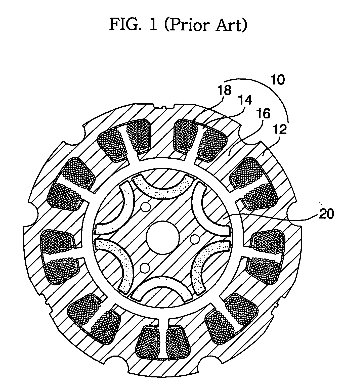
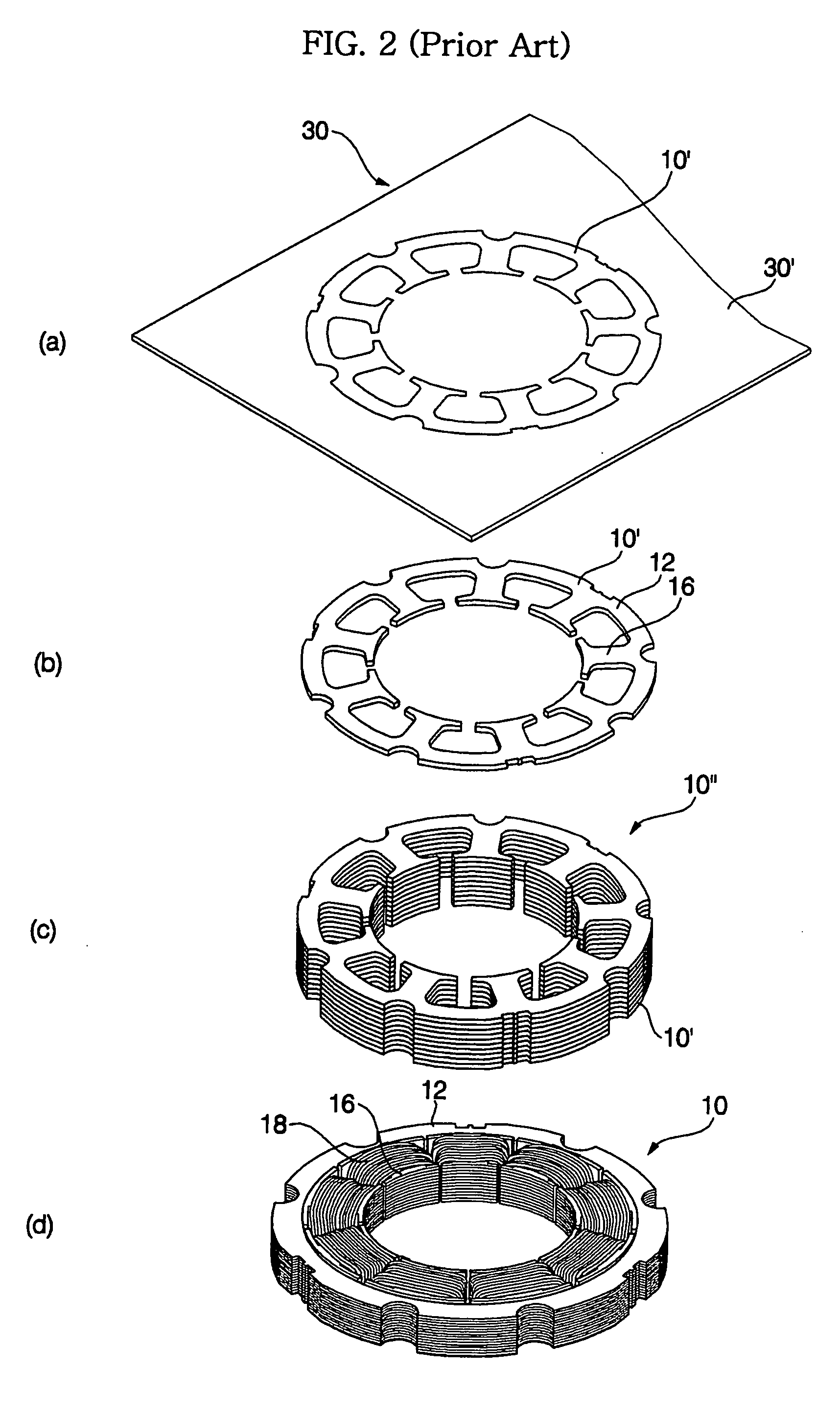
[0045] Several embodiments of the present invention may be described. Since the basic structure of the stator is identical to that of a stator of a conventional motor, a detailed description thereof will be omitted.

[0046] FIGS. 4 to 7 are views illustrating the stator of a motor according to the preferred embodiment of the present invention.

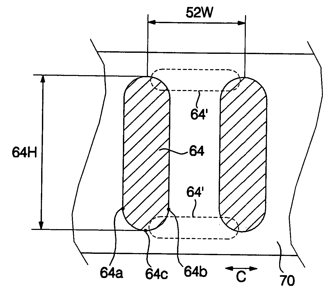
[0047] As shown in FIGS. 4 to 7, the stator S of a motor includes a plurality of teeth 60 spaced apart from each other in the circumferential direction (indicated by an arrow C) by slots 52 formed therebetween, a ring-shaped yoke 70 for integrating the teeth 60 in one body, and coils (not shown) wound around the teeth 60.

[0048] Each tooth 60 includes a tip 62 facing the rotor 50 in the radial direction, and a neck 64, disposed between the tip 62 and the yoke 70, on which the coil is wound.

[00...


PUM


Abstract

A stator of a motor having various shapes and capable of minimizing the manufacturing costs. At least teeth are manufactured by the iron powder metallurgy method. In order to obtain the overhang effect, the height of a tip of each tooth is lower than the height of a rotor and the height of a yoke is higher than the height of a tip of each tooth so as to minimize the core loss of the yoke. Since, in order to minimize the end coil, the height of a neck of each tooth is gradually higher as running from the sides to the central portion in the circumferential direction, costs for manufacturing a motor can be minimized and sufficient efficiency can be obtained.

Description

BACKGROUND OF THE INVENTION [0001] 1. Field of the Invention [0002] The present invention relates to a motor, and more particularly to a stator of a motor in which the height of each tooth's tip is lower than the height of a rotor and the height of a yoke is higher than the teeth's tip so that costs for manufacturing a motor is decreased and the efficiency of the motor is increased. [0003] 2. Description of the Related Art [0004] Generally, a motor generates a driving force by which a rotor is driven by electromagnetic interaction between a stator and the rotor. [0005]FIGS. 1 and 2 are views illustrating the stator of a conventional motor. [0006] A stator 10 of a motor, as shown in FIGS. 1 and 2, includes a ring-shaped yoke 12 disposed at the outside of a rotor 20, a plurality of teeth 16 protruding from the inner wall of the yoke 12 toward the rotor 20 in the radial direction, forming slots 14 therebetween to have a desired shape, and being spaced apart from each other, and coils 1...

Claims


Application Information

Patent Timeline
Patent Type & Authority Applications(United States)
IPC IPC(8): H02K1/28H02K1/12
CPCH02K1/02H02K21/16H02K1/148H02K1/146
Inventor SHIM, JANG HOPARK, JIN SOOKIM, BYUNG TAEK
Owner LG ELECTRONICS INC
Why Eureka
Try Eureka