
Randomized patterns of individual optical elements

a technology of individual optical elements and randomized patterns, applied in the field can solve the problems and the non-uniform brightness of light redirecting films that exhibit moiracute over (e) effects, and achieve the effect of reducing the quality of display

Inactive Publication Date: 2006-03-16
SKC HAAS DISPLAY FILMS CO LTD
View PDF6 Cites 50 Cited by
  • Summary
  • Abstract
  • Description
  • Claims
  • Application Information

AI Technical Summary

Benefits of technology

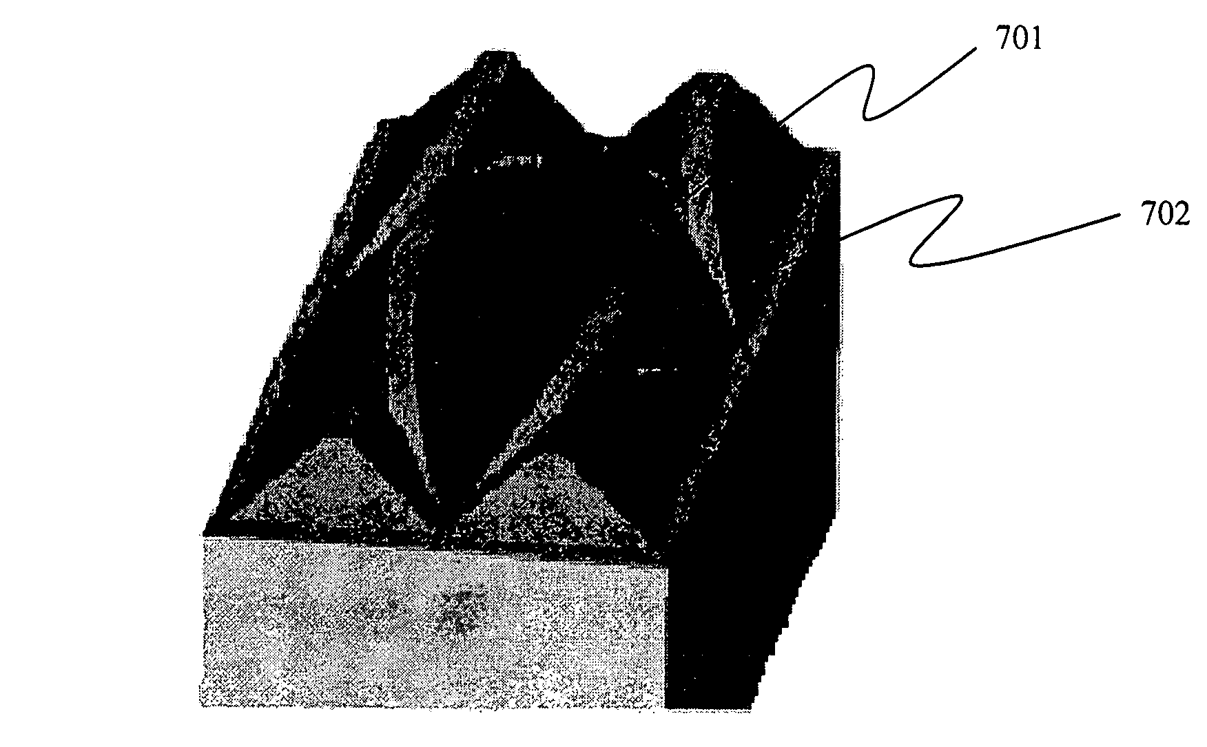
[0006] In accordance with an example embodiment, a method of randomizing elements into a random pattern on a surface so the random pattern of elements substantially entirely consumes a region of the surface includes choosing an overlap distance and creating an initial pattern of elements that substantially entirely consumes a region of the surface, wherein neighboring elements overlap by the overlap distance. The method also includes choosing a maximum displacement distance, and displacing the elements by random displacement distances from their positions in the initial pattern, the random displacement distances being less than the maximum displacement distance. Moreover, a signed difference in displacement between two neighboring elements is not greater than the overlap distance.
[0007] In accordance with another example embodiment, an apparatus includes a plurality of elements disposed in a substantially random pattern over a surface. Illustratively, the elements cover substantially all of a region of the surface and are disposed at random displacement distances from their positions in a reference pattern of elements in which neighboring elements overlap by an overlap distance. The displacement distances are less than a maximum displacement distance, and a signed difference in displacement between two of the neighboring elements is not greater than the overlap distance.

Problems solved by technology

However, there may be secondary effects of a light redirecting film (e.g., moiré effects or a moiré interference pattern) that reduce the quality of the display.
For example, light redirecting films that exhibit moir{acute over (e )} effects may have undesirable non-uniform brightness across the LCD screen.

Method used


Image

  • Randomized patterns of individual optical elements
  • Randomized patterns of individual optical elements
  • Randomized patterns of individual optical elements

Examples


Embodiment Construction

[0026] In the following detailed description, for purposes of explanation and not limitation, example embodiments disclosing specific details are set forth in order to provide a thorough understanding of the present invention. However, it will be apparent to one having ordinary skill in the art having had the benefit of the present disclosure, that the present invention may be practiced in other embodiments that depart from the specific details disclosed herein. Moreover, descriptions of well-known apparati and methods may be omitted so as to not obscure the description of the present invention. Such methods and apparati and methods are clearly within the contemplation of the inventors in carrying out the example embodiments. Wherever possible, like numerals refer to like features throughout.

[0027] Light redirecting films of the example embodiments may be thin transparent optical films or substrates that redistribute the light passing through the films such that the distribution of...


PUM


Abstract

A method of randomizing elements into a random pattern on a surface so the random pattern of elements substantially entirely consumes a region of the surface includes choosing an overlap distance and creating an initial pattern of elements that substantially entirely consumes a region of the surface, wherein neighboring elements overlap by the overlap distance. The method also includes choosing a maximum displacement distance, and displacing the elements by random displacement distances from their positions in the initial pattern, the random displacement distances being less than the maximum displacement distance. Moreover, a signed difference in displacement between two neighboring elements is not greater than the overlap distance. An apparatus including the elements is also disclosed.

Description

FIELD OF THE INVENTION [0001] Embodiments of the present invention relate to light redirecting films for redirecting light from a light source toward a direction normal to the plane of the film. BACKGROUND OF THE INVENTION [0002] Light redirecting films may be used in a variety of applications. Illustratively, light directing films may be used as part of a display or lighting device. Display and lighting devices may be based on a variety of technologies and can have very disparate applications. Regardless of the technology base or application, light directing films may be used to improve the efficiency of the light transmitted from a light source to an output. [0003] One technology that has gained attention in display technologies is liquid crystal (LC) technology. An LC display (LCD) includes a liquid crystal material that is modulated to provide a light-valve function. In many LCD applications, it is useful to improve the power efficiency. Increasing the power efficiency of an LCD...

Claims


Application Information

Patent Timeline
Patent Type & Authority Applications(United States)
IPC IPC(8): G09G5/00G09G3/36
CPCG02B5/0221G02B5/0278G02B5/045G02F1/133526G02B6/0065G02B27/095G02B6/0053G02B5/02G02F1/1335
Inventor WILSON, RANDALL H.
Owner SKC HAAS DISPLAY FILMS CO LTD
Learn More