Film scanner for color originals

a color original and film scanner technology, applied in the field of color original film scanners, can solve the problems of difficult to compensate for the loss of intensity, playback errors, and r, g and b images of a scene recorded chronologically, and achieve the effect of narrowing down the green region

Inactive Publication Date: 2006-03-16
DEUTSCHES ZENTRUM FUER LUFT & RAUMFAHRT EV
View PDF4 Cites 1 Cited by
  • Summary
  • Abstract
  • Description
  • Claims
  • Application Information

AI Technical Summary

Benefits of technology

[0012] In yet another preferred embodiment, the photosensitive sensor is designed as a matrix sensor, which can be used to record the entire image spectrum. To form the R, G, and B images, it is necessary merely to select the corresponding columns of the matrix. The particular advantage of this arrangement is that, first, the images can be recorded loss-free, which is very important for archival purposes. In addition, the red, green, and / or blue spectrum in question can be adjusted by combining the individual lines appropriately. This makes it possible, furthermore, to take into account certain spectral properties of the original. For example, the film original may have a different spectral distribution because of aging. The existing current spectral distribution can first be determined by pre-recording part of the film (without image content), and then the corrections can be made by selecting the appropriate lines in the spectrum. Instead of a pre-recorded image without image content, it is also possible to record several images and to average them. In concrete terms, it is possible, for example, to compensate for a greenish tinge in the film by narrowing down the green region of the spectrum.

Problems solved by technology

Regardless of the choice of light source, the problem occurs that the R, G, and B images of a scene are recorded in chronological succession.
Even the smallest variations in the speed of the film drive lead to synchronization difficulties, which result in playback errors.
It is not easy to compensate for the loss of intensity by increasing the brightness of the illumination of the slit in the film stage because then the exposed section of film is subjected to too much thermal stress.
The scanning rate must therefore be reduced, which is disadvantageous.

Method used


Image

  • Film scanner for color originals
  • Film scanner for color originals

Examples


Embodiment Construction

[0018] The invention is explained in greater detail below on the basis of a preferred exemplary embodiment.

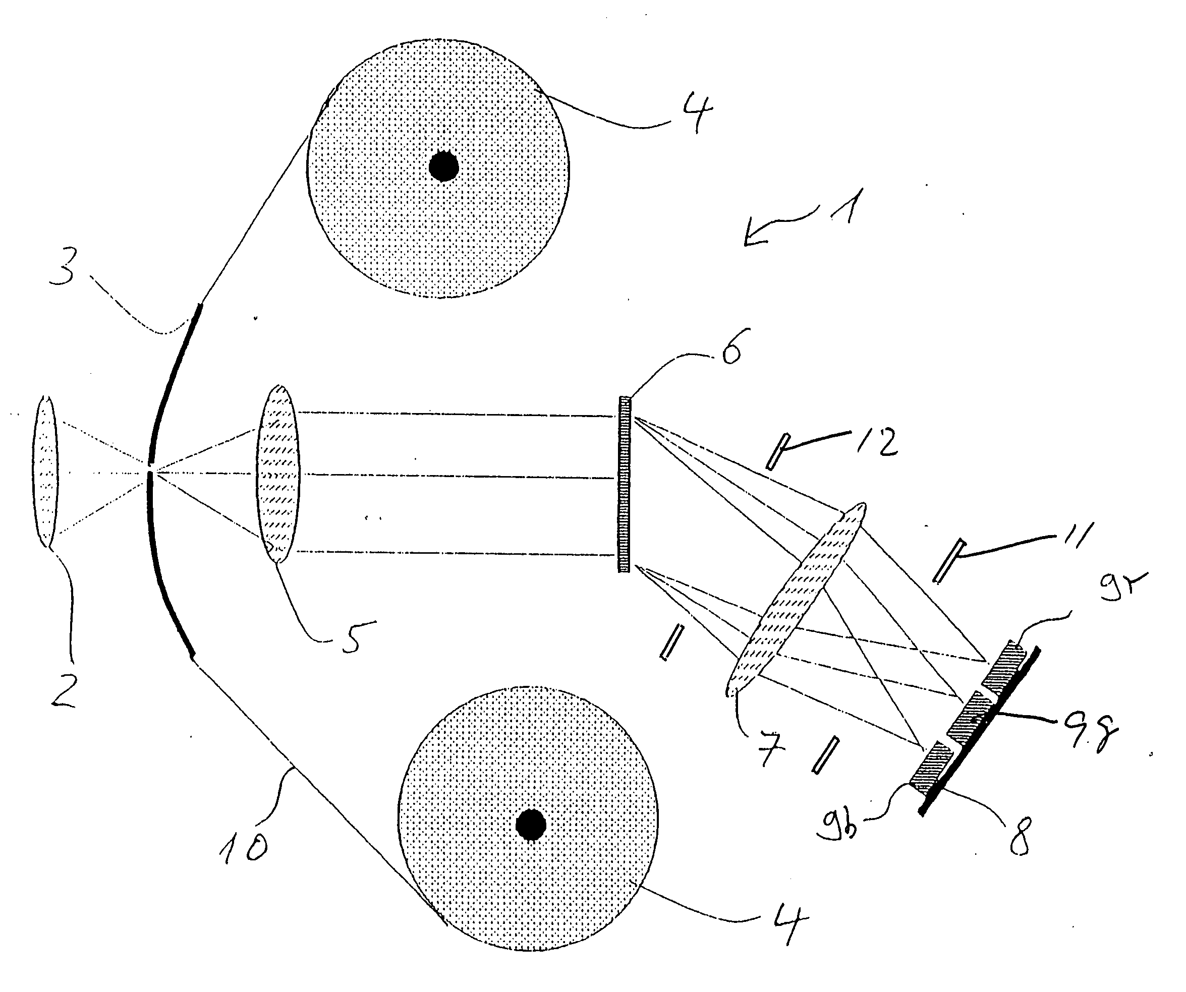
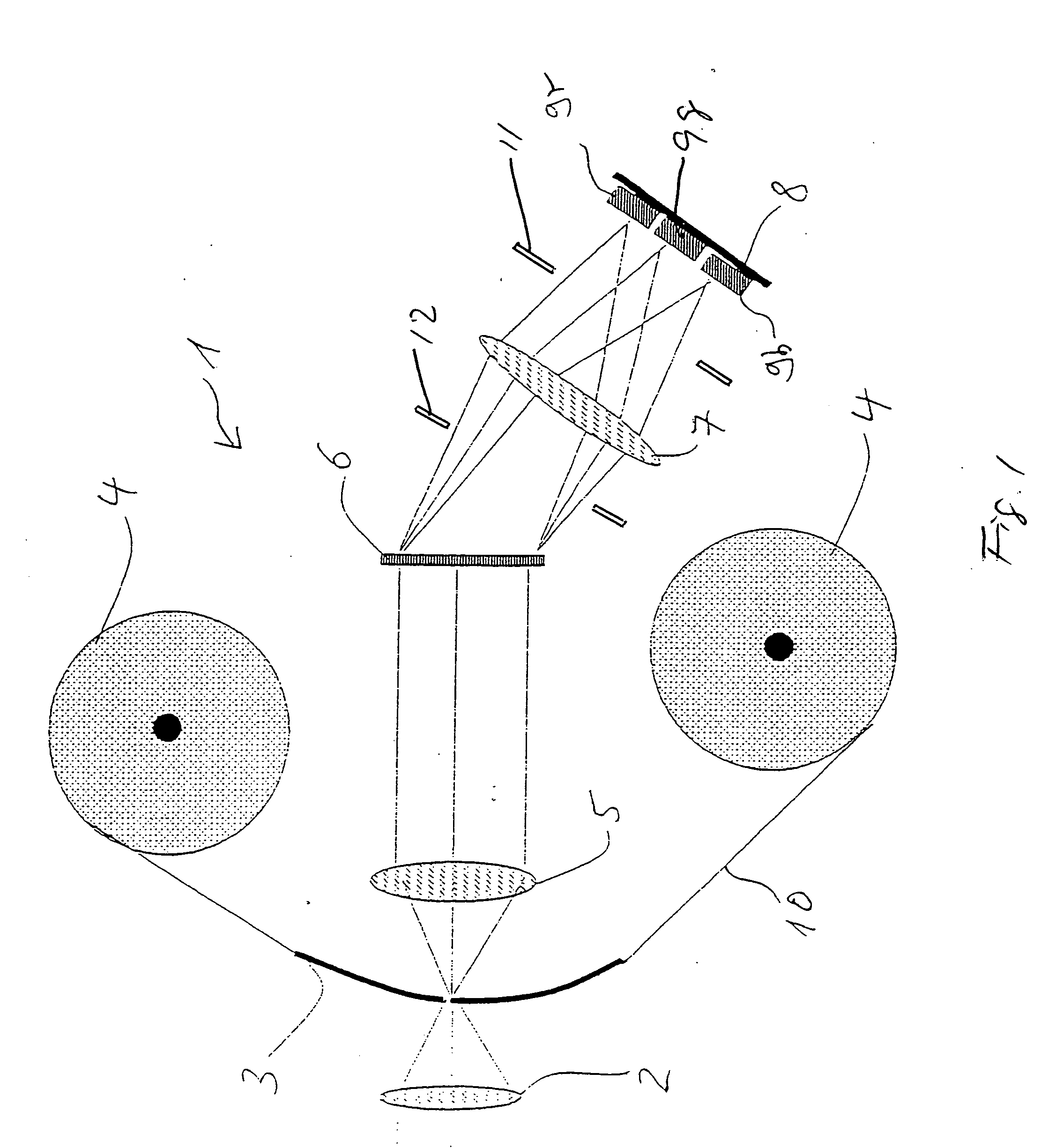
[0019] As shown in FIG. 1, the film scanner 1 comprises a source of white light (not shown), a first projection lens 5, a film stage 3, a film drive 4, a second projection lens 7, a spectrum-splitting element 6, a third projection lens 2, and a focal plane 8, on which three linear photosensitive sensors 9 are arranged. These are, for example, panchromatic CCD or CMOS linear sensors. The light emitted by the white light source is parallelized and projected through the third projection lens 2 onto a slit-shaped opening in the film stage 3. The film drive 4 conducts the film 10 to be scanned continuously past the slit-shaped opening. The first projection lens 5 then forms the image of the opening on the spectrum-splitting element 6, which, for example, is designed as a prism. By means of the second projection lens 7, the blue spectral components are projected onto the first senso...


PUM


Abstract

A film scanner for a color original comprises a film stage having a slit-shaped opening, the slit-shaped opening generating an image of the color original when the color original is moving across the film stage while the slit-shaped opening is illuminated by a source of white light; a photosensitive sensor; and a spectrum-splitting element positioned between the film stage and the photosensitive sensor for dividing the image of the color original into its spectral components. The photosensitive sensor is oriented so that desired regions of the spectral components strike the photosensitive sensor. A process for scanning a color original is also disclosed.

Description

PRIORITY CLAIM [0001] The application claims the priority of German patent application number 10 2004 045 559.7, filed Sep. 15, 2004. BACKGROUND OF THE INVENTION [0002] 1. Field of the Invention [0003] The invention relates to a film scanner for color originals and a process for scanning color originals. [0004] 2. Description of the Related Art [0005] Most film scanners for color originals are based on the principle of producing separate red (“R”), green (“G”), and blue (“B”) images, which are stored and then reassembled into a color image at the time of playback. [0006] There are two different approaches to the production of R, G, and B images. According to the first approach, a separate opening is provided in the film stage for each image. When spectrally selective light sources are used, the light source in question is assigned to its opening, and the corresponding spectrally selective image is recorded. When white-light sources are used, color filters must be either integrated i...

Claims


Application Information

Patent Timeline
Patent Type & Authority Applications(United States)
IPC IPC(8): H04N5/253
CPCH04N3/38H04N9/11H04N9/097H04N23/16
Inventor HUBERS, HEINZ-WILHELMECKARDT, ANDREASDRIESCHER, HANS
Owner DEUTSCHES ZENTRUM FUER LUFT & RAUMFAHRT EV
Why Eureka
Try Eureka