Projection optical system

a technology of projection optical system and projection optical system, which is applied in the field of projection optical system, can solve the problems of poor image surface flatness, rays striking the enlargement conjugate surface at sharp, and the projection optical system disclosed in the patent publications 1 to 3 does not contribute to satisfactory slimming down of the projection apparatus as a whole, so as to achieve good optical performance and reduce cost. , the effect of being advantageous in terms of mass production

Inactive Publication Date: 2006-03-16
KONICA MINOLTA OPTO
View PDF9 Cites 19 Cited by
  • Summary
  • Abstract
  • Description
  • Claims
  • Application Information

AI Technical Summary

Benefits of technology

[0011] In view of the conventionally encountered problems mentioned above, it is an object of the present invention to provide a projection optical system that, despite offering good optical performance, is advantageous in terms of mass production and cost reduction, is slim, and is composed of lightweight, compact optical components.

Problems solved by technology

The projection optical systems disclosed in Patent Publications 1 to 3 do not contribute to satisfactory slimming-down of projection apparatuses as a whole.
One problem with this approach is that it produces a strong positive Petzval sum, resulting in poor image surface flatness.
Another problem is that the negative mirror, with a curved surface, tends to cause interference when it turns the optical path.
The problem here is that the use of the Fresnel reflective surface causes rays to strike the enlargement conjugate surface at sharp angles relative thereto at the periphery of the projected image.
This induces surface reflection at the periphery of the screen, resulting in lower brightness there and thus uneven brightness in the projected image.

Method used


Image

  • Projection optical system
  • Projection optical system
  • Projection optical system

Examples


examples

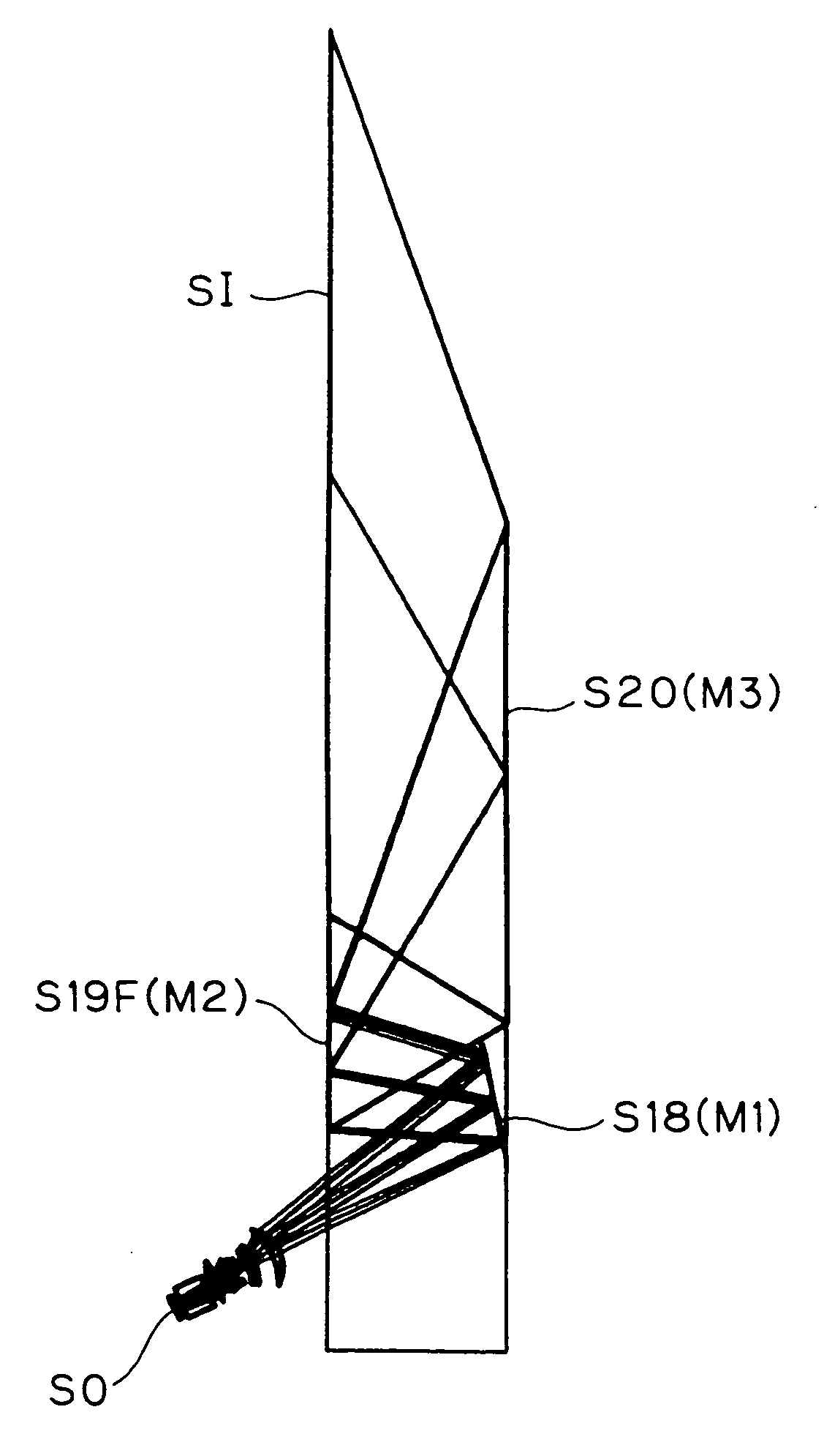
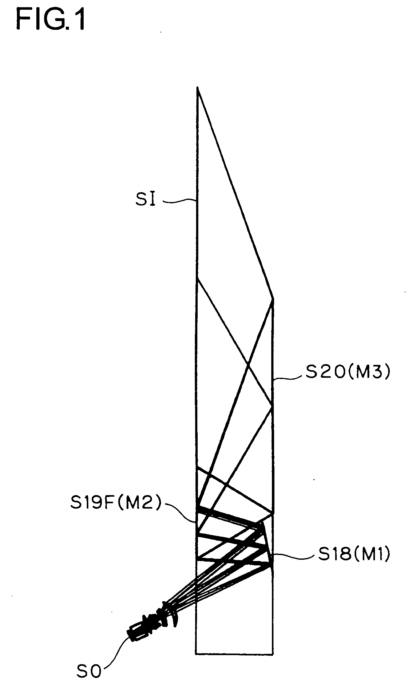
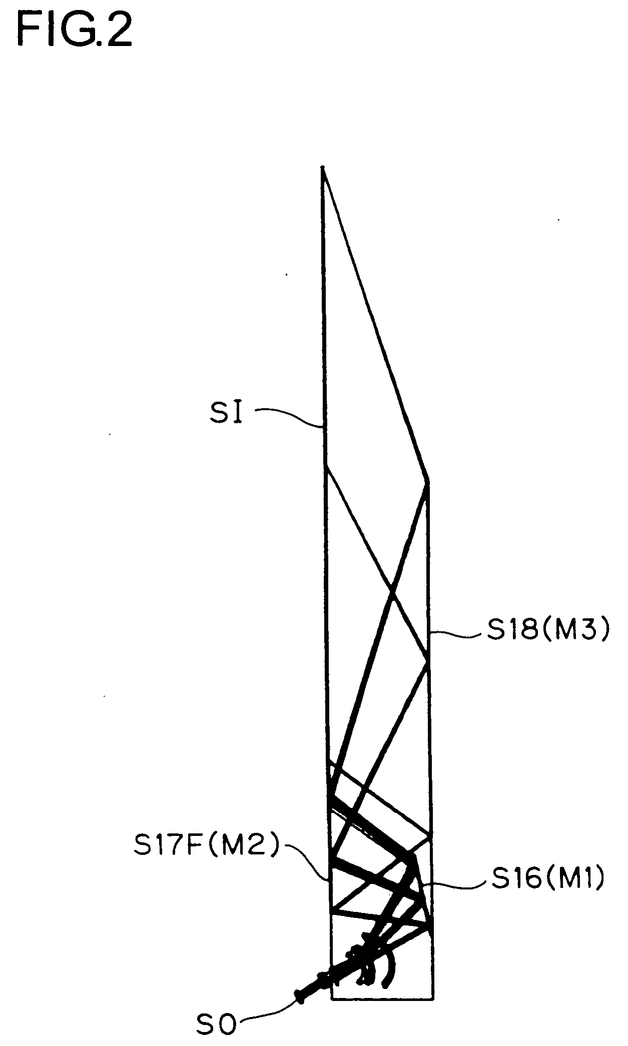
[0060] Hereinafter, practical examples of projection optical systems embodying the present invention will be presented with references to their construction data and other data. Examples 1 to 5 presented below are numerical examples corresponding to the first to fifth embodiments, respectively, described above, and therefore the optical construction diagrams (FIGS. 1 to 10) showing the respective embodiments also show the optical construction, projection optical path, and other features of the corresponding examples.

[0061] Tables 1 to 24 show the optical construction of Examples 1 to 5. Of these tables, Tables 1 and 2, Tables 6 and 7, Tables 10 and 11, Tables 15 and 16, and Tables 20 and 21 show, for Examples 1 to 5, respectively, the optical arrangement throughout the entire optical system including the primary image surface (SO, corresponding to the object surface in enlargement projection) on the reduction side to the secondary image surface (SI, corresponding to the image surfa...


PUM


Abstract

A projection optical system for performing enlargement projection from a primary image surface located on the reduction side to a secondary image surface located on the enlargement side has, from the secondary image surface side, at least two reflective surfaces. Of the first and the second reflective surface counted from the secondary image surface side, at least one has a negative optical power. At least one Fresnel reflective surface having a positive or negative optical power is disposed within the entire projection optical system.

Description

[0001] This application is based on Japanese Patent Application No. 2004-46307 filed on Feb. 23, 2004, the contents of which are hereby incorporated by reference. BACKGROUND OF THE INVENTION [0002] 1. Field of the Invention [0003] The present invention relates to a projection optical system, and more particularly to, for example, a projection optical system that has a reflective Fresnel optical element incorporated in an optical construction suitable for rear projection. [0004] 2. Description of Related Art [0005] In a projection optical system that performs enlargement projection from a primary image surface located on the reduction side to a secondary image surface located on the enlargement side, disposing a negative mirror closer to the secondary image surface in the optical path is effective in obtaining a wider angle of view. Examples of projection optical systems that use a negative mirror to obtain a wider angle of view are proposed, for example, in Patent Publications 1 to ...

Claims


Application Information

Patent Timeline
Patent Type & Authority Applications(United States)
IPC IPC(8): G02B3/00G02B17/00G02B17/06G02B17/08G02B27/18G03B21/00
CPCG02B17/0812G02B17/0852G02B17/0832
Inventor KUWA, TOMIEI
Owner KONICA MINOLTA OPTO
Why Eureka
Try Eureka