

Telephoto lens system
- Summary
- Abstract
- Description
- Claims
- Application Information
AI Technical Summary
Benefits of technology
Problems solved by technology
Method used
Image

Examples
embodiment 1
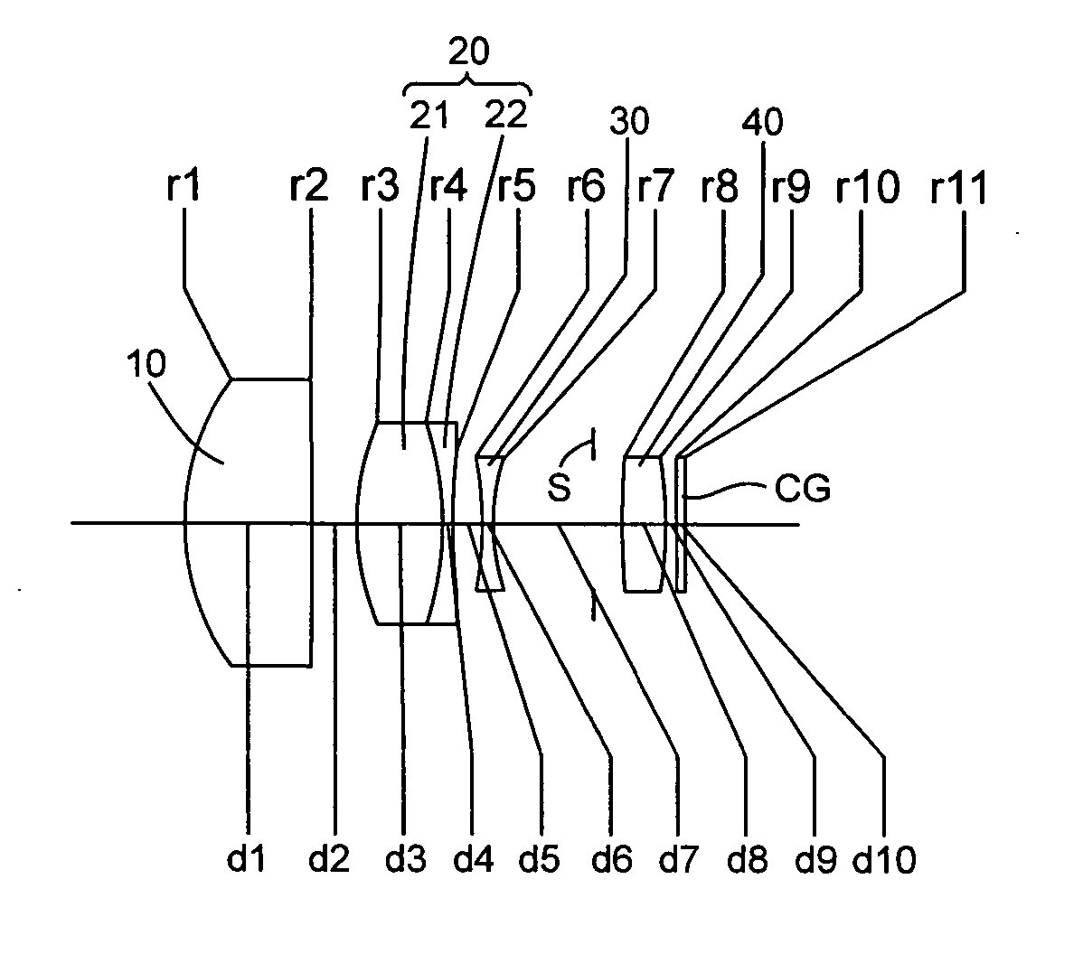
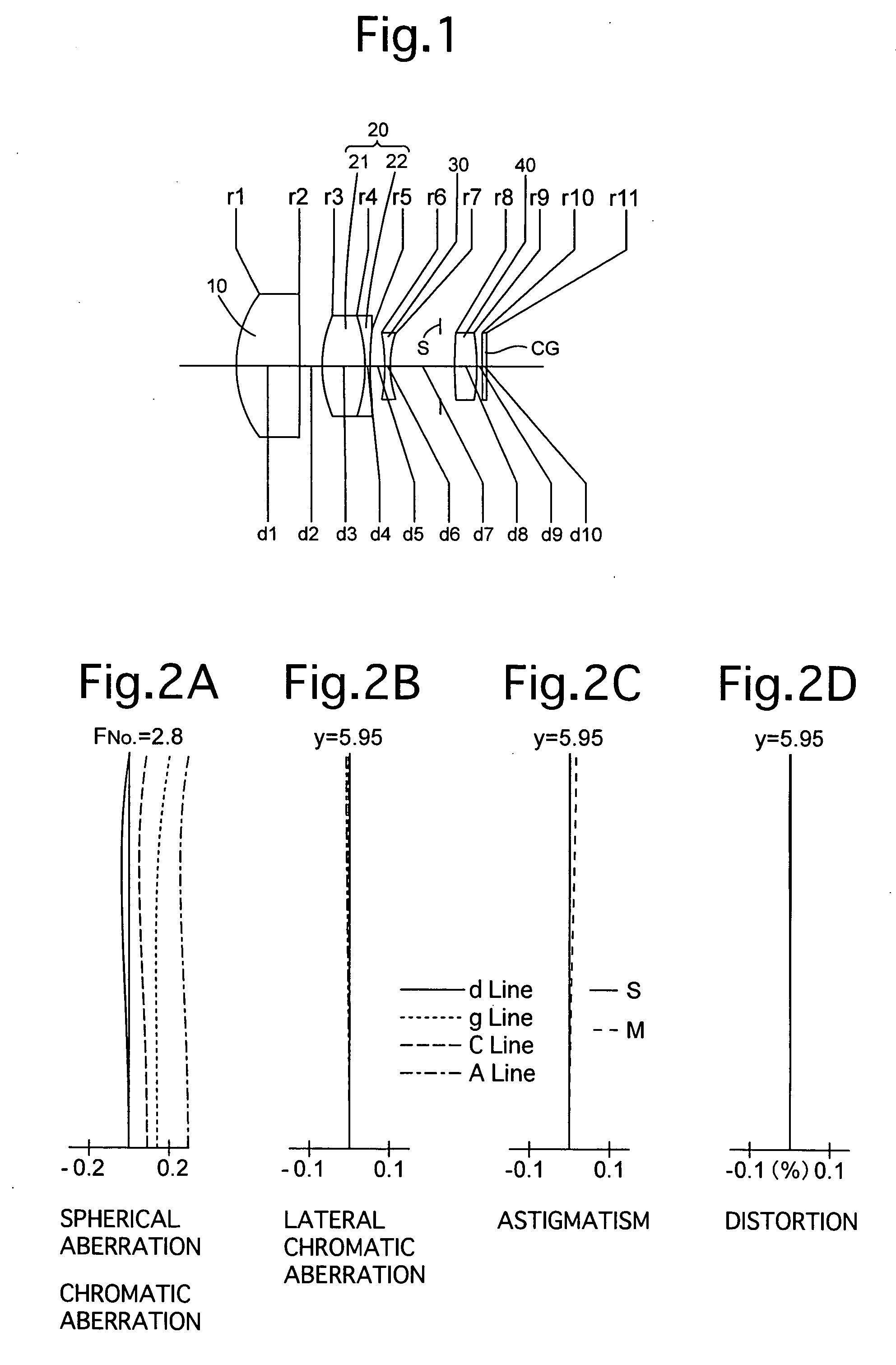
[0092]FIG. 1 is the lens arrangement of the telephoto lens system according to the first embodiment of the present invention. FIGS. 2A through 2D show aberrations occurred in the lens arrangement shown in FIG. 1. Table 1 shows the numerical data of the first embodiment.
[0093] The telephoto lens system includes a biconvex positive lens element 10 (first lens group) having a convex surface with a large curvature facing toward the object, cemented lens elements 20 (second lens group) having a biconvex positive lens element 21 and a biconcave negative lens element 22 in this order from the object, a biconcave negative lens element 30 (third lens group), a diaphragm S, and a biconvex positive lens element 40 (fourth lens group), in this order from the object. Here, note that the refractive power of the second lens group 20 is negative.
[0094] A cover glass CG (surface Nos. 10 and 11) is provided behind the positive fourth lens group 40.
[0095] The diaphragm S is provided 8.640 behind (o...
embodiment 2
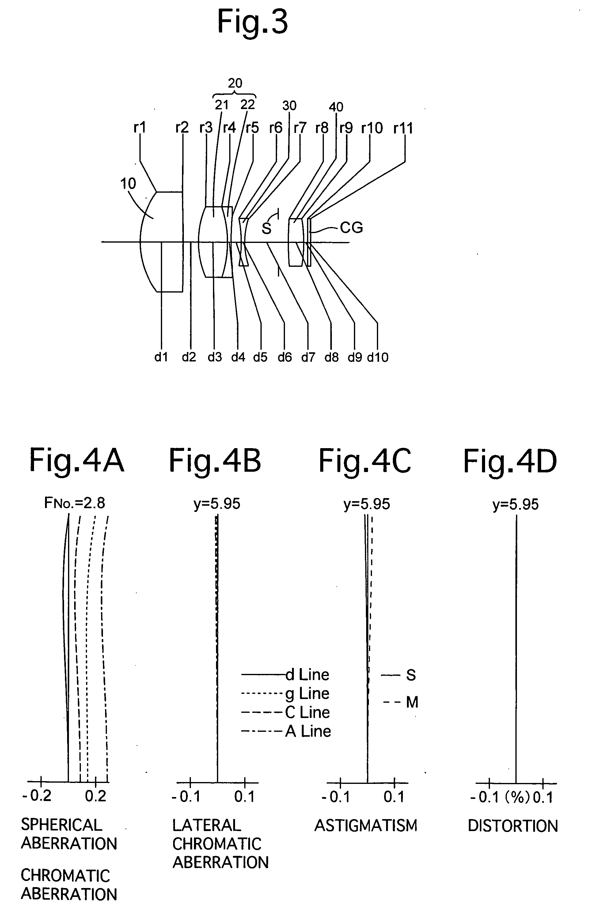
[0096]FIG. 3 is the lens arrangement of the telephoto lens system according to the second embodiment of the present invention. FIGS. 4A through 4D show aberrations occurred in the lens arrangement shown in FIG. 3. Table 2 shows the numerical data of the second embodiment.
[0097] The lens arrangement of the telephoto lens system of the second embodiment is the same as that of the first embodiment. Here, note that the refractive power of the second lens group 20 is negative.
[0098] The diaphragm S is provided 8.640 behind (on the image side of) the negative third lens group 30 (surface No. 7).
TABLE 2FNO. = 1:2.8 (an object at infinity is in an in-focus state)f = 72.78m = −0.377fB = 57.41y = 5.95Surf. No.rdNdν121.95511.001.5163364.12−654.0533.91323.5647.461.4560090.34−29.6150.901.8340037.2571.5332.646−31.3810.901.6699839.3719.58311.18884.2383.921.8040046.69−38.1741.0010 ∞0.751.5163364.111 ∞—
embodiment 3
[0099]FIG. 5 is the lens arrangement of the telephoto lens system according to the third embodiment of the present invention. FIGS. 6A through 6D show aberrations occurred in the lens arrangement shown in FIG. 5. Table 3 shows the numerical data of the third embodiment.
[0100] The lens arrangement of the telephoto lens system of the third embodiment is the same as that of the first embodiment. Here, note that the refractive power of the second lens group 20 is negative.
[0101] The diaphragm S is provided 8.640 behind (on the image side of) the negative third lens group 30 (surface No. 7).
TABLE 3FNO. = 1:2.8 (an object at infinity is in an in-focus state)f = 72.78m = −0.376fB = 57.04y = 5.95Surf. No.rdNdν121.66711.001.5163364.12−928.0053.91322.9367.461.4387595.04−28.8510.901.8340037.2577.3612.646−31.5780.901.6699839.3719.26411.18881.3803.921.8040046.69−38.2551.0010 ∞0.751.5163364.111 ∞—
PUM
 Abstract
Description
Claims
Application Information