
Device and method for detecting mass concentration of particulate matter

A mass concentration and particulate matter technology, which is applied in the direction of measuring devices, particle suspension analysis, suspension and porous material analysis, etc., can solve the problems of large result error, large environmental impact, frequent parameter correction, etc., and achieve fast response speed and mass resolution. High efficiency, accurate and reliable measurement results

Inactive Publication Date: 2018-01-19
HEILONGJIANG UNIVERSITY OF SCIENCE AND TECHNOLOGY
View PDF9 Cites 8 Cited by
  • Summary
  • Abstract
  • Description
  • Claims
  • Application Information

AI Technical Summary

Problems solved by technology

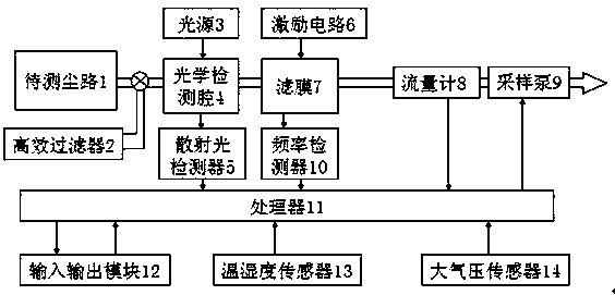
[0008] In order to solve the technical problems of the existing device and method for detecting the concentration of particulate matter, such as high cost, great influence on the environment, frequent correction of parameters, and large error in results, the present invention provides a device and method for detecting the mass concentration of particulate matter. The light scattering measurement unit and the microresonance measurement unit are set side by side on the road. First, the light scattering method is used for multiple measurements. According to the residual error and standard deviation of the multiple measurement results, it is determined that the gas path to be tested needs microresonance measurement and correction. The average concentration and measurement error obtained by the two methods are fused and calculated, and finally the mass concentration of particulate matter in the gas path to be tested is obtained

Method used


Image

  • Device and method for detecting mass concentration of particulate matter
  • Device and method for detecting mass concentration of particulate matter
  • Device and method for detecting mass concentration of particulate matter

Examples


Embodiment 1

[0028]A device for detecting the mass concentration of particulate matter, including a gas path to be tested 1, an airflow driving device, a light scattering measurement unit and a flow metering unit arranged on the gas path 1 to be tested, and a supporting control processor, and also includes a light scattering measurement unit The unit is set on the same micro-resonance measurement unit on the gas path to be tested, and the micro-resonance measurement unit includes a blocking filter 7 arranged on the gas path to be measured and a frequency detector 10 connected to the blocking filter 7 and a control circuit , the signal output terminal of the frequency detector 10 is connected with the control processor.

[0029] The light scattering measurement unit includes a light source 3, an optical detection cavity 4 arranged on the gas path 1 to be measured, and a scattered light detector 5 connected to the optical detection cavity 4, and the signal output terminal of the scattered lig...

Embodiment 2

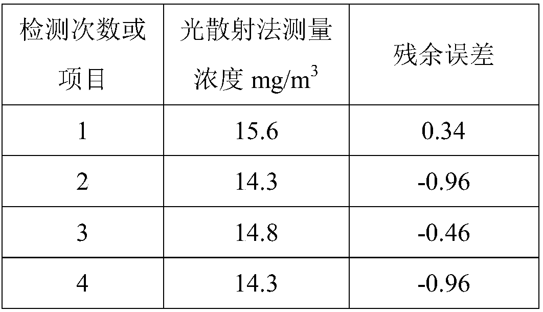
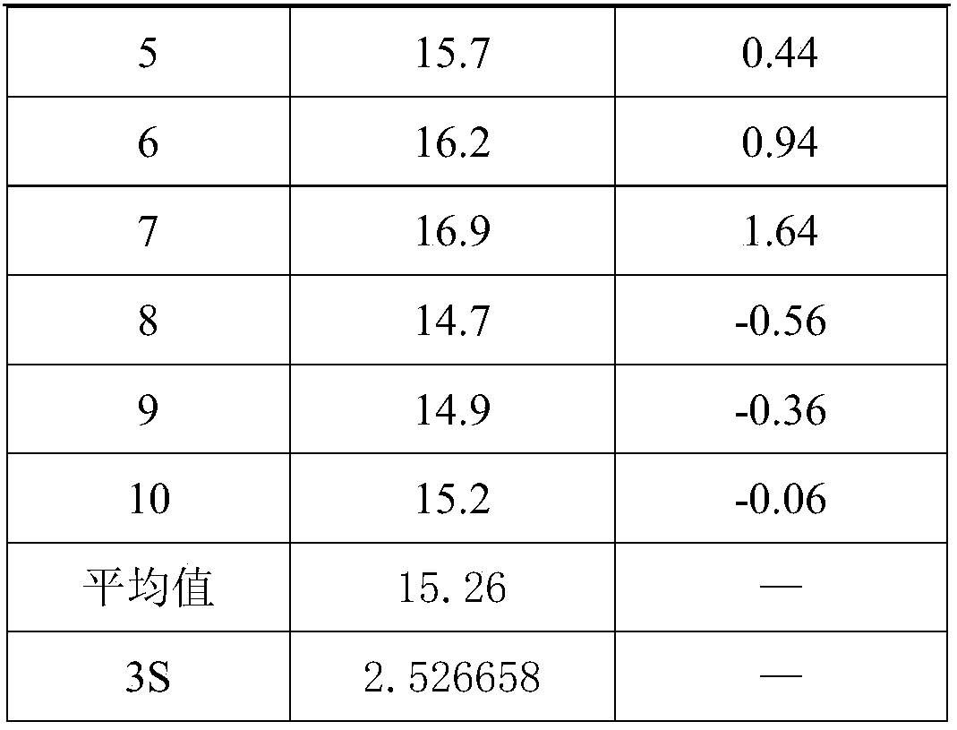
[0041] The relative humidity of the control environment is less than 80% RH, and the temperature is 20±5°C. The dust with low concentration and poor uniformity collected in the field is used as the sample to be tested, and the airflow drive device is turned on to disperse the sample to be tested within 1m. 3 In the air, the mass concentration is adjusted to 3.5mg / m 3 , and further make the dust to be tested form an airflow to pass through the gas path 1 to be tested. The detection time is longer than 4 hours. First, the scattered light is detected 10 times in a row by the light scattering measurement unit. The control processor automatically calculates the results as shown in Table 2:

[0042] Table 2 Measurement results of light scattering measurement unit

[0043]

[0044]

[0045] Comparison found that the light scattering method measurement results show that the average concentration of 3.18, and 3.5mg / m 3 The gap is large, and in the residual error |v i |greater t...

Embodiment 3

[0051] ①The relative humidity of the control environment is less than 80% RH, the temperature is 20±5°C, and standard experimental dust (ISO12103) is used, respectively, through the light scattering measurement system and the fusion measurement including the light scattering measurement unit and the micro-resonance measurement unit of the present invention Method system, using time of more than 8 hours, respectively measured the concentration of standard dust, the experimental data are as follows:

[0052] Table 1 Experimental data of standard dust detection

[0053]

[0054] It can be seen from the above results that the measured average value and variance of the light scattering measurement method are larger, and the concentration value fluctuation of the standard dust measured by the fusion measurement method system comprising the light scattering measurement unit and the micro-resonance measurement unit of the present invention is smaller, and the variance is far away. ...


PUM


Abstract

The invention provides a device and a method for detecting the mass concentration of a particulate matter, and relates to the technical field of concentration detection. The device for detecting the mass concentration of the particulate matter comprises a gas channel to be measured, a gas flow driver, and a light scattering measurement unit, a flow metering unit and a matched control processor which are arranged on the gas channel to be measured, and also comprises a micro-resonance measurement unit arranged on the same gas channel to be measured together with the light scattering measurementunit, the micro-resonance measurement unit includes a choked flow filter membrane arranged on the gas channel to be measured, and a frequency detector and a control circuit which are connected with the choked flow filter membrane, and the signal output end of the frequency detector is connected with the control processor. The device and the method, which adopt a micro-resonance process and a lightscattering measurement process to carry out fusion calculation, have the advantages of high mass resolution, fast response speed, suitableness for various gas channels, overcoming of the influences of the physical, chemical and flow characteristics of particles on the simple light scattering measurement process, and accuracy and reliability in the measurement result.

Description

technical field [0001] The invention relates to the technical field of concentration detection, in particular to a device and method for detecting the mass concentration of particulate matter. Background technique [0002] Atmospheric environment is an important condition for people to survive and develop, and particulate matter in the environment is a major hazard to people's health and life, especially in recent years, pM2.5 and pM10 have become increasingly serious, and people have paid more and more attention to the concentration of particulate matter in the environment . The pollution caused by the pollution source of coal-fired power plants is very serious. All countries in the world are studying and controlling it. It is necessary to detect the concentration of smoke and dust emitted. At present, the better methods include light scattering method, β-ray method, and micro-resonance method. [0003] The principle of the light scattering method is: after the light sourc...

Claims


Application Information

Patent Timeline
Patent Type & Authority Applications(China)
IPC IPC(8): G01N15/06
Inventor 刘丹丹汤春瑞曹亚迪汝红芳郝文亮梁永波李景贺
Owner HEILONGJIANG UNIVERSITY OF SCIENCE AND TECHNOLOGY
Learn More