Controller for a disk, disk enclosure device, disk array apparatus, method for detecting a fault of disk enclosure device, and signal-bearing medium

a technology of enclosure device and control device, which is applied in the direction of maintaining head carrier alignment, recording information storage, instruments, etc., can solve the problems of b>63/b> and the output of the id setting signal cannot be stopped

Inactive Publication Date: 2006-03-16
NEC CORP
View PDF16 Cites 1 Cited by
  • Summary
  • Abstract
  • Description
  • Claims
  • Application Information

AI Technical Summary

Benefits of technology

[0042] The first effect is that the ID code setting signal is checked in two controllers configured with redundancy, so that each ID code setting switch can be checked for a wrong setting.
[0043] The second effect is that each controller provided in a disk disclosure checks each ID code setting signal with use of the bus switch, thereby transistor faults are detected.
[0044] The third effect is that each returned value is checked by turning OFF / ON the bus switch of each controller, thereby bus switch faults are detected.
[0045] The fourth effect is that each controller is provided with a bus switch, thereby the output of the ID code setting signal can be stopped in case that a wrong setting in an ID code setting switch and part faults are detected.

Problems solved by technology

However, the conventional disk enclosure device 10a has been confronted with the following problems.
The second problem is that the output of the ID setting signal 53, 63 cannot be stopped even when a fault occurs in a part of the disk enclosure device 10a.

Method used


Image

  • Controller for a disk, disk enclosure device, disk array apparatus, method for detecting a fault of disk enclosure device, and signal-bearing medium
  • Controller for a disk, disk enclosure device, disk array apparatus, method for detecting a fault of disk enclosure device, and signal-bearing medium
  • Controller for a disk, disk enclosure device, disk array apparatus, method for detecting a fault of disk enclosure device, and signal-bearing medium

Examples


Embodiment Construction

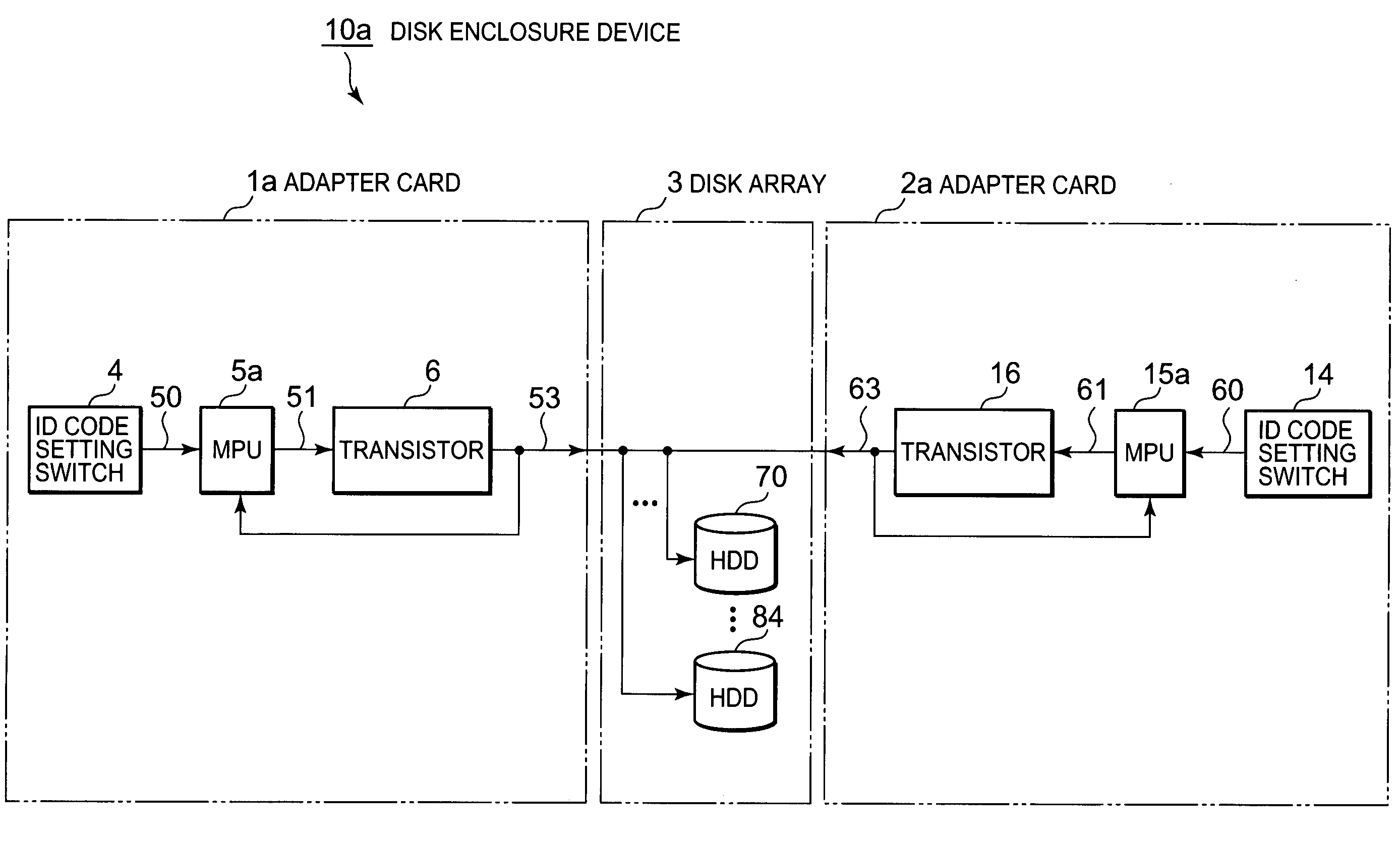
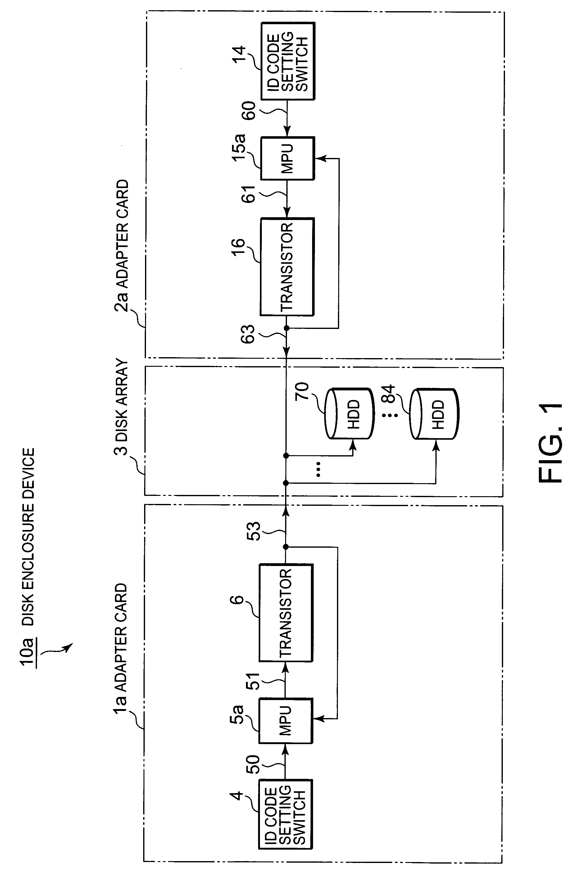
[0051] Hereunder, the exemplary embodiments of the present invention will be described with reference to the accompanying drawings. It is noted that the “controller,”“comparator” or “digital processing apparatus,” and “memory unit” in the scope of the claims are more concretely referred to as an “adapter card” and a “microprocessor” or “MPU,” and “disk array 3” respectively in the following discussion.

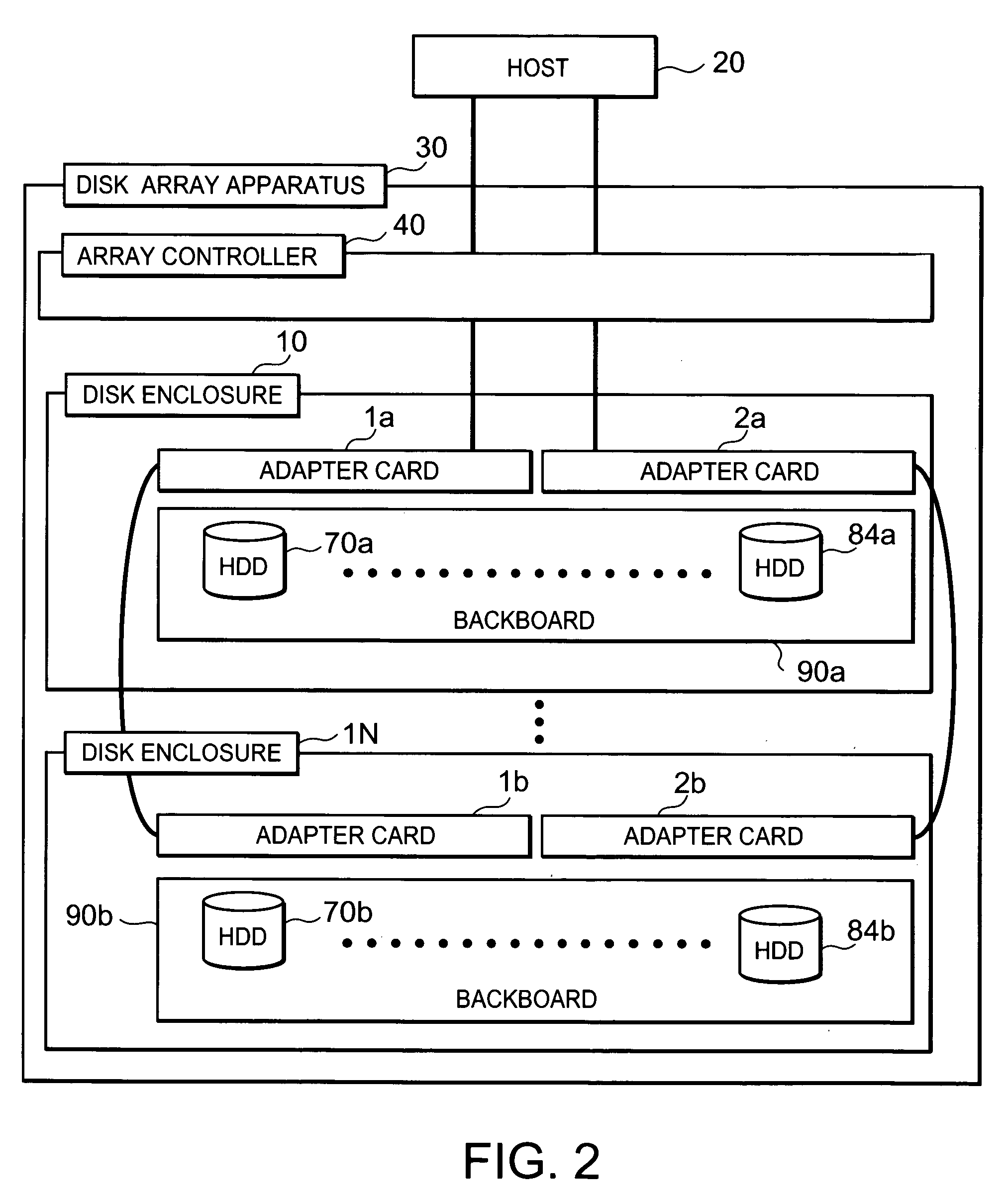
[0052]FIG. 2 is a block diagram of a disk array apparatus 30 and a host 20. The disk array apparatus 30 includes array controller 40 and a plurality of disk enclosures 10 to IN. Each of disk enclosures 10 . . . 1N includes a backboard 90a . . . 90b. Adapter card 1a and adapter card 2a, and HDDs 70a . . . 84a are plugged into the backboard 90a. Similarly two adapter cards 1b, 2b, and HDDs 70b . . . 84b are plugged into the backboard 90b.

[0053] Array controller 40 controls the overall operation of disk array apparatus 30. The host is connected to disk array apparatus 30.

[0054]FIG. 3 i...


PUM


Abstract

A method and structure for a controller for a memory unit includes a switch that provides a first identification code for the memory unit and a comparator that compares the first identification code with at least a second identification code for the memory unit.

Description

FIELD OF THE INVENTION [0001] The present invention relates to a disk enclosure device for a disk array configured to control a disk with use of two controllers configured with redundancy and to a media control program employed for the same. BACKGROUND OF THE INVENTION [0002] In a conventional method of controlling disk drives, as described in Japanese Patent Laid-Open No. 64-019456, each magnetic disk drive is provided with an identification (ID) code setting switch. This ID code setting switch comprises, for example, a DIP (dual inline package) switch that can set a value in bits as a binary code. A central processing unit (CPU) of the disk device controls the magnetic disk drive according to the ID code set with the ID code setting switch. [0003] In a conventional method, there is also a disk enclosure device for a disk array configured to control a disk with use of two controllers configured with redundancy. FIG. 1 shows a block diagram of such a disk enclosure device 10a. Hereu...

Claims


Application Information

Patent Timeline
Patent Type & Authority Applications(United States)
IPC IPC(8): G11B5/596
CPCG06F11/2089
Inventor WAKAMATSU, YOSHINORI
Owner NEC CORP
Why Eureka
Try Eureka