Method for manufacturing tool for analysis

Inactive Publication Date: 2006-03-16
ARKRAY INC
View PDF27 Cites 8 Cited by
  • Summary
  • Abstract
  • Description
  • Claims
  • Application Information

AI Technical Summary

Benefits of technology

[0008] An object of the present invention is to provide a method of manufacturing an analytical tool having a reage

Problems solved by technology

Due to this, the production of the pressure rod 94 becomes difficult, and disadvantageous in terms of production cost.
Accordingly, the surface pressurizing techni

Method used


Image

  • Method for manufacturing tool for analysis
  • Method for manufacturing tool for analysis
  • Method for manufacturing tool for analysis

Examples


Embodiment Construction

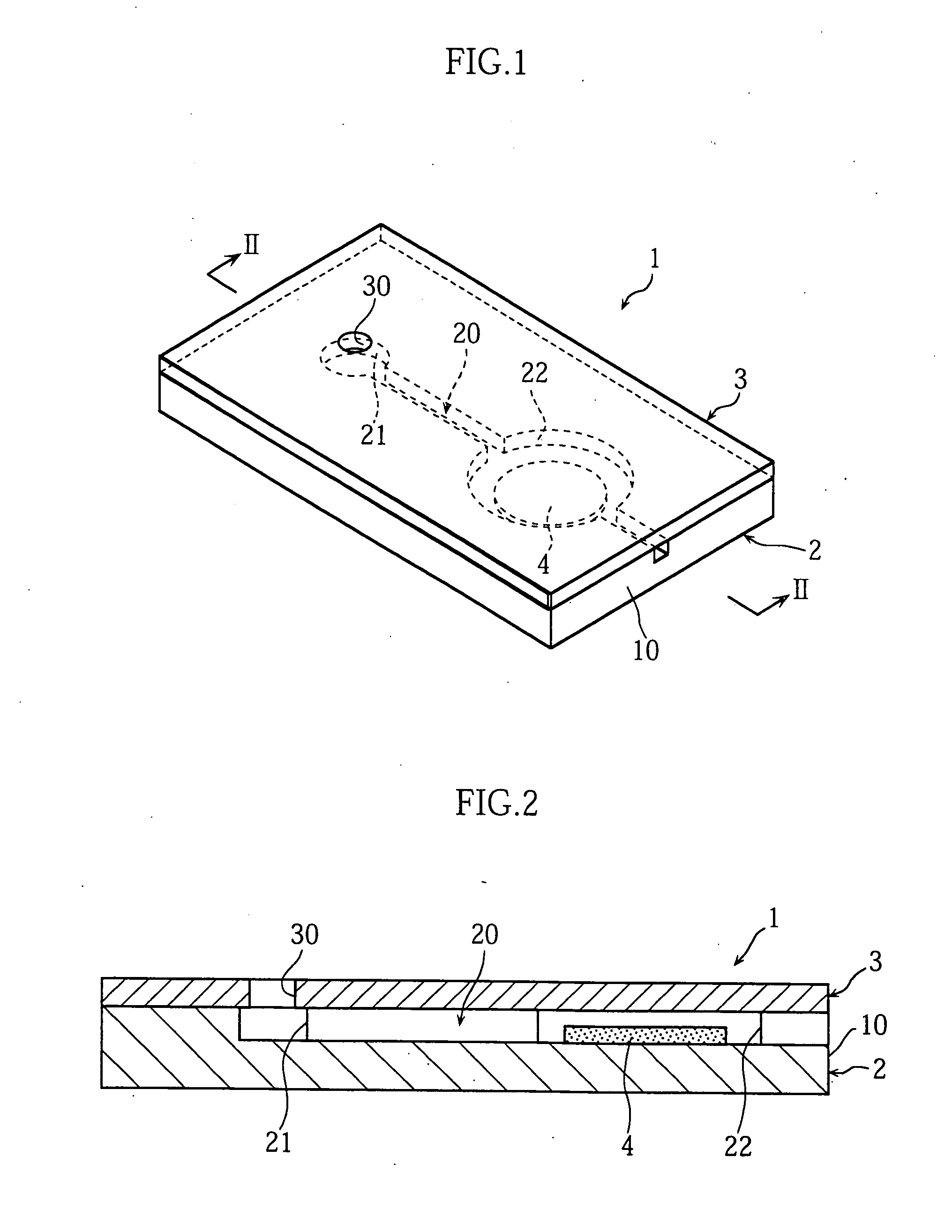
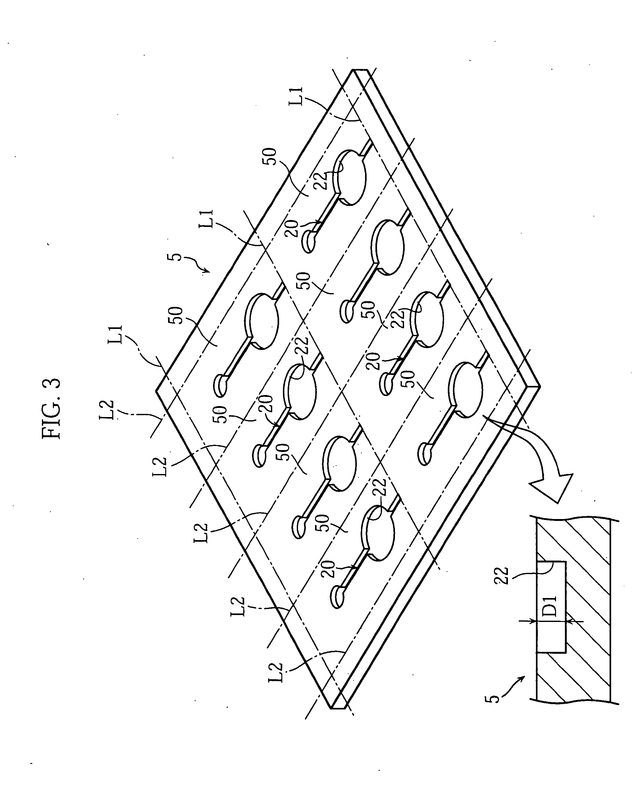
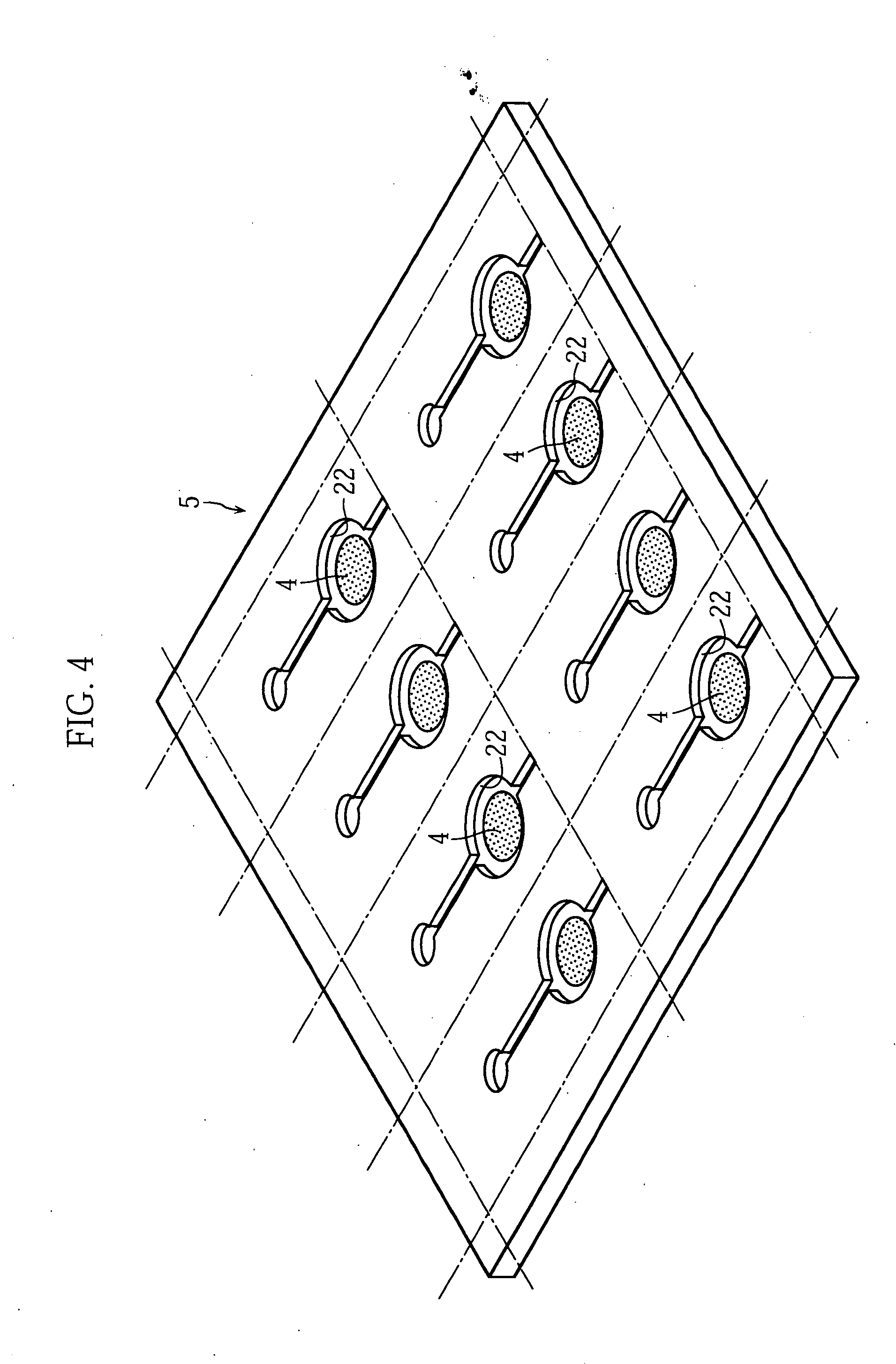
[0028] The present invention relates to a method of manufacturing analyzing tools. Before the description of the method, an example of the analyzing tool made by the method is described referring to FIGS. 1 and 2.

[0029]FIGS. 1 and 2 illustrate an analytical tool 1 which is a micro device adapted for analyzing a very small amount of sample. In the analytical tool 1, the sample liquid is caused to move by capillary action, and provides a reaction field. The analytical tool 1 includes a base plate 2 formed with a very narrow path 20 and a cover 3 arranged on the base plate for covering the path 20. The path 20 includes a liquid receiving portion 21 and a reagent holding portion 22, and is open at an end face 10 of the analytical tool 1. The reagent holding portion 22 is provided with a reagent member 4 containing a reagent that reacts with a specific component in the sample liquid. The cover 3 is formed with an inlet port 30 communicating with the liquid receiving portion 21 of the ba...


PUM


Abstract

The present invention relates to a method of manufacturing an analytical tool, where the method includes a reagent member forming process for preparing a reagent member containing a reagent to react with a specific component contained in sample liquid. The reagent member forming process includes a plurality of applying and drying steps in which material liquid containing a reagent is applied and then the material liquid is dried. The applying and drying steps may be performed with use of material liquid containing the same reagent, for example. The applying and drying steps are performed 2-200 times, for example.

Description

TECHNICAL FIELD [0001] The present invention relates to a method of manufacturing an analytical tool used for analyzing a specific component contained in a sample. Specifically, the analytical tool to be made includes a reagent member provided with a reagent that reacts with the specific component. BACKGROUND ART [0002] A known example of sample-analyzing methods employs an optical technique for analyzing reaction liquid resulting from the reaction between the sample and a reagent. In analyzing a sample with such an technique, use is made of an analytical tool that provides a reaction field. In particular, to analyze a small amount of sample, a micro device formed with an arrow flow path is used as the analytical tool. The reaction between the sample and the reagent on the analytical tool can be caused by supplying the sample to a reagent member formed on the analytical tool. [0003] The reagent member of the analytical tool is formed by providing a reaction site 90 with material liq...

Claims


Application Information

Patent Timeline
IPC IPC(8): G01N1/28G01N33/543G01N31/20A21C11/16B01L3/00G01N31/22G01N37/00
CPCA21C11/163B01L3/5085B01L2400/0406B01L2200/16B01L2300/0816B01L2200/12
Inventor HIROSHI, FUKUYANAKAMURA, TSUTOMUAONO, TAKAFUMI
Owner ARKRAY INC
Why Eureka
Try Eureka