System and method for measuring radiation characteristic of antenna

Active Publication Date: 2006-03-16
THE IND & ACADEMIC COOPERATION & CHUNGNAM NAT UNIV +2
View PDF8 Cites 7 Cited by
  • Summary
  • Abstract
  • Description
  • Claims
  • Application Information

AI Technical Summary

Benefits of technology

[0015] It is an object of the present invention to provide an antenna measurement system which can quickly and precisely measure the radiation characteristic of a source antenna (the phase, or the intensity or amplitude) using micro tester antennas and IC chips, thereby obtaining correct far-field range data.
[0016] It is another object of the present invention to provide an antenna measurement method which measures the radiation characteristic of a source antenna (the phase, or the intensity or amplitude) by arranging a plurality of measurement modules at a plane or sphere-shaped tester body each with a micro tester antenna and an IC chip, thereby obtaining correct far-field range data within a short period of time.

Problems solved by technology

The elevated range and the slant range involve lower cost for the installation and measurement of the relevant elements, but practically require very wide area and high tower, with the disadvantage of being much influenced by the external weather.
The anechoic chamber involves the indoor measurement, and is not influenced by the external weather, with the disadvantage in that much cost is needed to make a large laboratory (for example, making it with a vertical length of 10 m, a horizontal length of 10 m and a height of 5 m) with absorbents.
As various objects such as trees, forests, hills, rivers and buildings are existent between the source antenna and the tester antenna, it is very difficult to make the correct measurement, and to quickly cope with the variable measurement situations.
Moreover, with the case of the far-field range, the source antenna is exposed to the outside to obtain the correct measured values, and hence, it becomes difficult in the radar or military antennas to make the desired measurement while keeping a secret.
The compact range is desirably installed within the relatively small space, but it undesirably requires a large-scaled reflector.
However, as the probe should precisely move in the X and Y axial directions to correctly figure a predetermined plane (the plane perpendicular to the central axis of the source antenna) within the short distance, much time and cost are consumed to make the equipment for moving the probe (the tester antenna), and to make the desired measurement.
The anechoic chamber also involves the same problem as with the near-field range in that the measurement is made using a probe.
As the carrier for moving the probe very precisely is made with a high cost of up to hundreds of millions, it is practically difficult with the small-scale companies to make measurement experiments related to the development of antennas in a sufficient manner.
As the measurement is made while moving the probe in a slight manner, several hours are consumed even to make the measurement once, and this means that considerable time is wholly needed to complete the required measurements.
Furthermore, with the high possibility of making errors in the measuring due to the variable environmental conditions, it becomes impossible to make the total inspection with respect to the produced antennas, and only the deficient sampling test can be made.
In order to obtain more correct far-field range data, it is required to enlarge the mobile range (the plane area) of the probe, but such an enlargement is practically limited due to the carrier for moving the probe.
Furthermore, the carrier for moving the probe is liable to generate electromagnetic waves, which are applied to the measured values as noises.
Furthermore, with the case of the near-field range and the anechoic chamber, as the measurement is made only to the front side of the source antenna, it is impossible to make correct expressions for the back lobe.

Method used


Image

  • System and method for measuring radiation characteristic of antenna
  • System and method for measuring radiation characteristic of antenna
  • System and method for measuring radiation characteristic of antenna

Examples


first embodiment

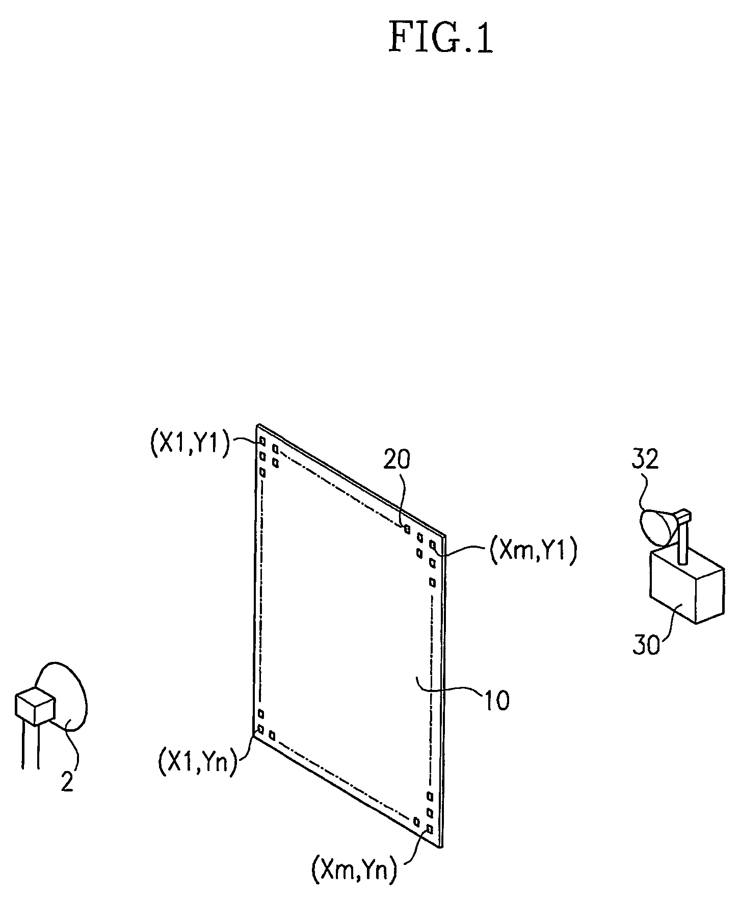
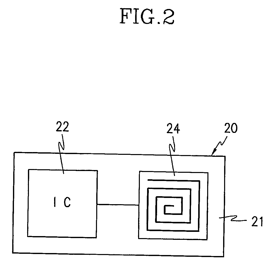
[0041]FIG. 1 is a schematic perspective view of an antenna measurement system according to the present invention, and FIG. 2 is a plan view of a measurement module for the antenna measurement system shown in FIG. 1.

[0042] As shown in FIGS. 1 and 2, the antenna measurement system includes a tester body 10 placed distant from a source antenna 2 by a predetermined distance, a plurality of measurement modules 20 arranged at the tester body 10 in a predetermined pattern, and a measurement controller 30. Each measurement module 20 has an IC chip 22 for processing the positional information and the measured values to generate the relevant signals, and a tester antenna 24 for receiving and transmitting the signals from the IC chip 22. Upon receipt of the frequency signals from the source antenna 2, the tester antenna 24 generates induced power for driving the IC chip 22, and transmits the measured values for the frequency signals to the IC chip 22. The measurement controller 30 receives the...

second embodiment

[0089]FIG. 14 illustrates an antenna measurement system according to the present invention.

[0090] As shown in FIG. 14, the tester body 12 is shaped with a sphere, and the measurement modules 20 are arranged on the inner surface of the tester body 12 in a predetermined pattern.

[0091] It is preferable to store the number characteristic to the installation location of the respective measurement modules 20 at the IC chip 22 using the coordination value (θ, φ) with the angle (θ) to the z axis and the angle (φ) to the x axis.

[0092] In case the tester body 12 is formed with a spherical shape, it is bisected into upper and lower parts. With this structure, it is easy to install and replace the source antenna 2 within the tester body 12.

[0093] The source antenna 2 is fixed to a support 3 placed at the lower part of the tester body 12 such that it is positioned at the center of the spherical shaped structure. It is preferable to structure the source antenna 2 such that the height thereof c...

third embodiment

[0098]FIG. 15 illustrates an antenna measurement system according to the present invention.

[0099] As shown in FIG. 15, the tester body 14 is formed with a semi-spherical shape, and the measurement modules 20 are arranged internal to the tester body 14 in a predetermined pattern.

[0100] The characteristic positional number of each measurement module 20 is input into the IC chip 22 using the coordination value (θ, φ) with the angle (θ) to the z axis and the angle (φ) to the x axis.

[0101] The structure of the tester body 14 according to the third embodiment of the present invention is the same as the upper part of the tester body 12 according to the second embodiment. In the case of the antennas installed on the ground, it is not needed to measure the characteristic thereof directed toward the ground, and hence, the structure according to the third embodiment is more effective than that according to the second embodiment.

[0102] Furthermore, when the tester body 14 is formed with a se...


PUM


Abstract

An antenna measurement system is provided to measure the radiation characteristic of a source antenna (2), and obtain more correct far-field range data within a short period of time. The antenna measurement system includes a tester body placed apart from the source antenna (2) with a predetermined distance. A plurality of measurement modules (20) are arranged at the tester body in a predetermined pattern. Each measurement module has an IC chip (22) for processing positional information and measured values to generate relevant signals, and a tester antenna for receiving and transmitting the signals from the IC chip (22). Upon receipt of frequency signals from the source antenna (2), the tester antenna (24) generates induced power for driving the IC chip (22), and transmits the measured values for the frequency signals to the IC chip (22). A measurement controller (30) receives the signals from the tester antenna (24), and data-processes the positional information and the measured values of the respective measurement modules (20).

Description

BACKGROUND OF THE INVENTION [0001] (a) Field of the Invention [0002] The present invention relates to a system and a method for measuring the radiation characteristic of an antenna, and more particularly, to an antenna measurement system and an antenna measurement method which speedily measure the radiation characteristic of a source antenna using micro-scaled test antennas and IC chips. [0003] (b) Description of the Related Art [0004] Generally, among the antenna ranges which are used to measure the radiation characteristic (the phase, or the intensity or amplitude) of the antenna, are there a far-field range where the measurement is made while the source antenna is placed far from the tester or receiver antenna, a near-field range where the measurement is made by using the source antenna as a transmitter and taking samples near to source antenna with a probe per a predetermined distance, and a compact range where the measurement is made while the source antenna is placed near to a...

Claims


Application Information

Patent Timeline
IPC IPC(8): H03J7/32H01Q1/00G01R29/10
CPCG01R29/10H01Q1/00
Inventor WOO, JONG-MYUNGKIM, JONG-LAE
Owner THE IND & ACADEMIC COOPERATION & CHUNGNAM NAT UNIV
Why Eureka
Try Eureka