Measuring apparatus

a technology of measuring apparatus and measuring rod, which is applied in the direction of measurement devices, instruments, interferometers, etc., can solve the problems of long measurement time, limited measuring accuracy, and high cost of measuring apparatus, and achieve the effect of quick and precise measuremen

Active Publication Date: 2013-03-14
CANON KK
View PDF5 Cites 18 Cited by
  • Summary
  • Abstract
  • Description
  • Claims
  • Application Information

AI Technical Summary

Benefits of technology

[0006]The present invention provides a measuring apparatus configured to quickly and precisely measure a shape of a test surface.

Problems solved by technology

However, the white light interferometer disclosed in JP 4,554,385 requires 105 image pickups or more for a measurement range of 100 mm even if the wide-range measuring interval is set to about several micro millimeters and thus is impractical due to enormous measurement times and a long measurement time period.
The optical frequency comb interferometer disclosed in JP 3,739,987 utilizes two optical frequency comb sources and causes the measuring apparatus to be expensive.
In addition, the measuring accuracy is limited due to the relative phase noises between these two optical light sources.
Moreover, since the optical frequency comb interferometer disclosed in JP 3,739,987 condenses the test beam upon the test surface and measures the position of the test surface, scanning a spot position is necessary to measure the shape of the test surface and thus the measurement takes a long time.

Method used


Image

  • Measuring apparatus
  • Measuring apparatus
  • Measuring apparatus

Examples


first embodiment

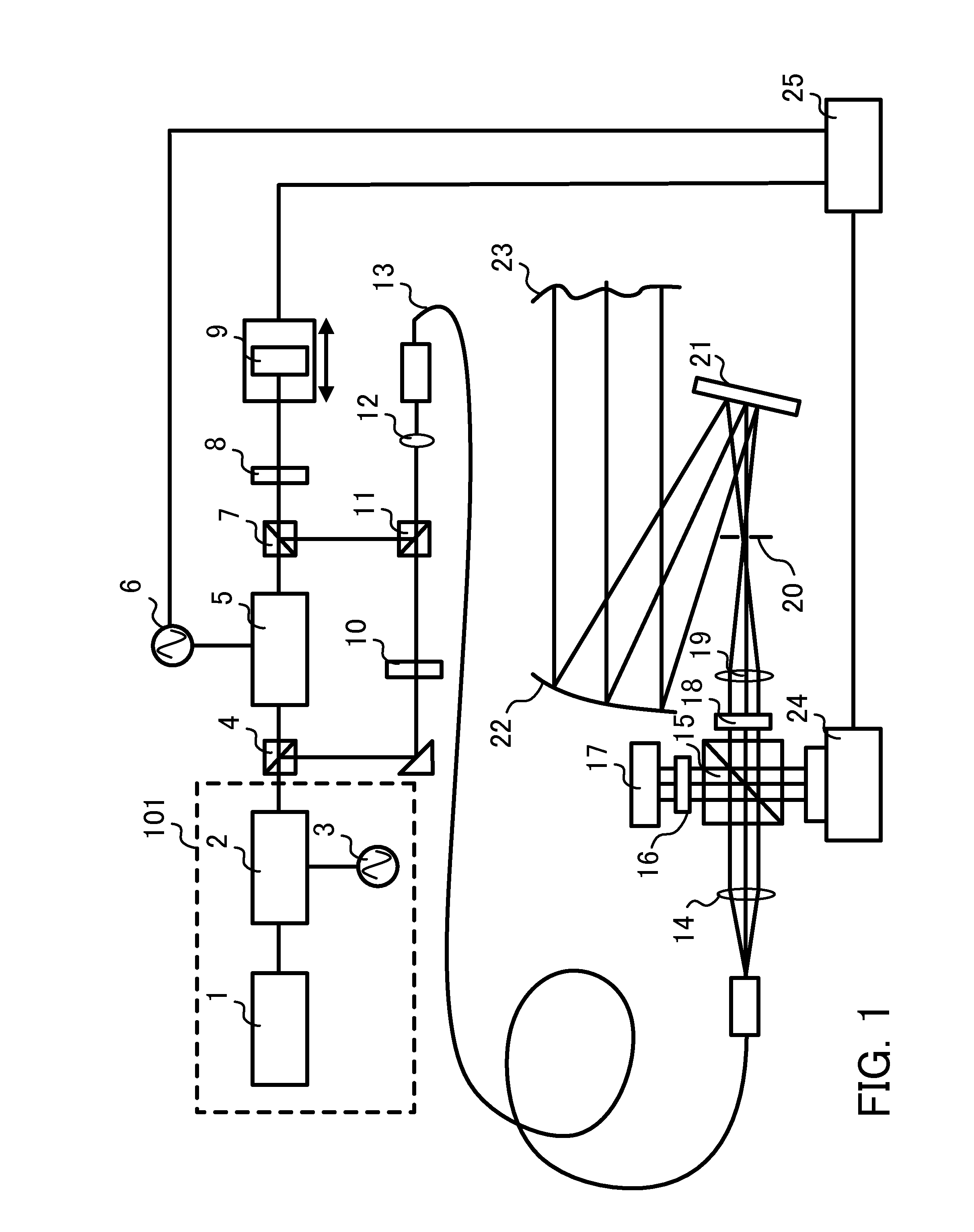
[0016]FIG. 1 is a block diagram of a measuring apparatus according to a first embodiment. The measuring apparatus include a single optical frequency comb source 101, a polarization beam splitter (“PBS”) 15 configured to split incident light into a test beam and a reference beam, a delay element 9 configured to delay the test beam and the reference beam, an image sensor 24 configured to capture an interference pattern, and an analyzer 25 configured to calculate a position of a test surface. The analyzer 25 is a controller configured to control an operation of each component in the measuring apparatus, and to execute calculation processing used to calculate the shape (position) of the test surface based upon the measurement result.

[0017]The optical frequency comb source 101 includes a distributed-feedback (“DFB”) laser 1, an optical frequency comb generator (“OFCG”) 2, and an oscillator 3, and emits an optical frequency comb. Unlike JP 3,739,987, a single optical frequency comb source...

second embodiment

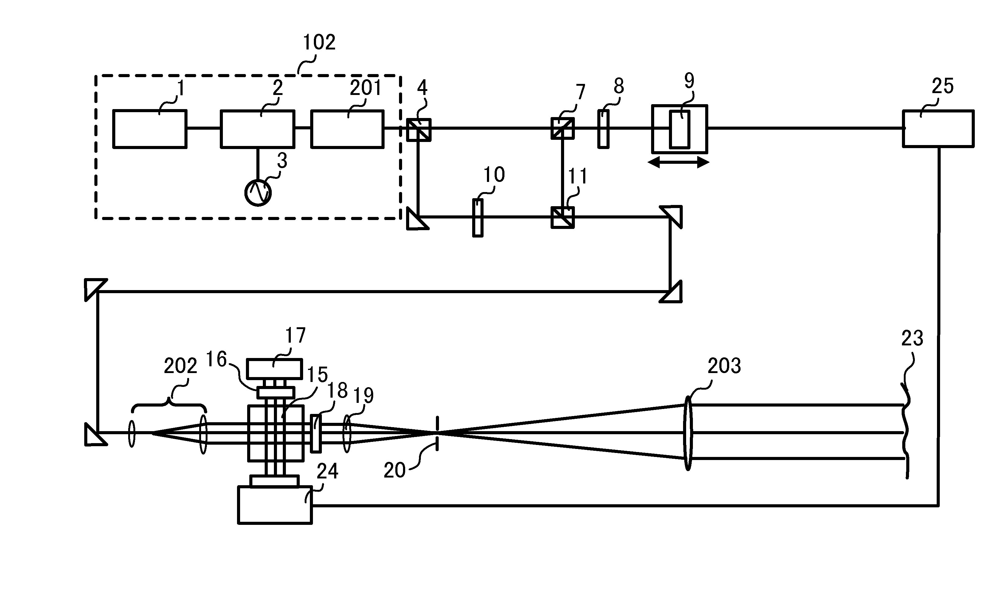
[0051]FIG. 5 is a block diagram of a measuring apparatus according to a second embodiment. The measuring apparatus of this embodiment is different from that of the first embodiment in that the optical frequency comb source 102 includes an etalon 201 configured to widen the frequency interval and the delay element 9 stops in the image pickup. Those elements in FIG. 5, which are the corresponding elements in FIG. 1, will be designated by the same reference numerals.

[0052]The optical frequency comb source 102 is made by attaching the etalon 201 to the OFCG 2 in the optical frequency comb source 101. A single optical frequency comb source 102 is provided.

[0053]The elements up to the OFCG 2 are similar to those of the first embodiment, and the optical frequency comb with a central frequency of f0 and the frequency interval of fm is emitted from the OFCG 2 and enters the etalon 201. The etalon 201 has FSR that is integer N times as many as fm, and the transmission spectrum of the etalon 2...


PUM


Abstract

A measuring apparatus includes an optical frequency comb source configured to emit an optical frequency comb in which a plurality of frequency components are arranged at equal frequency intervals, a beam splitter configured to split a beam emitted from the optical frequency comb source into a test beam to be irradiated onto a test surface and a reference beam to be irradiated onto a reference surface, an optical path difference changing element configured to change an optical path difference between the reference beam and the test beam, an image sensor configured to capture an interference pattern formed by interference between the test beam and the reference beam, and an analyzer configured to calculate a position of the test surface based upon a signal of the interference pattern captured while the optical path length difference is being changed by the optical path difference changing element.

Description

BACKGROUND OF THE INVENTION[0001]1. Field of the Invention[0002]The present invention relates to a measuring apparatus configured to measure a position of a test surface.[0003]2. Description of the Related Art[0004]Japanese Patent No. (“JP”) 4,554,385 proposes a white light interferometer configured to separate scanning of a test surface position into a wide-range measuring interval and a micro measuring interval, and to provide scanning with the micro measuring intervals for each wide-range measuring interval. JP 3,739,987 proposes an optical frequency comb interferometer configured to measure a test surface position without scanning a test or reference surface by utilizing an optical frequency comb for test and reference beams and by setting different frequency intervals.[0005]However, the white light interferometer disclosed in JP 4,554,385 requires 105 image pickups or more for a measurement range of 100 mm even if the wide-range measuring interval is set to about several micro ...

Claims


Application Information

Patent Timeline
Patent Type & Authority Applications(United States)
IPC IPC(8): G01B9/02
CPCG01B9/02008G01B9/02002G01B9/0209G01B11/2441G01B2290/60G01B9/02065G01B9/02069G01B2290/70G01B9/02014
Inventor KURAMOTO, YOSHIYUKI
Owner CANON KK
Why Eureka
Try Eureka