Optimizing ultrasound acquisition based on ultrasound-located landmarks

a landmark and ultrasound technology, applied in the field of optimizing ultrasound acquisition based on ultrasoundlocated landmarks, can solve the problems of unacceptably high inter-observer variability between echo-centers, affecting the evaluation of cardiac wall function, and many of the new parameters are difficult or impossible to assess directly

Inactive Publication Date: 2006-03-16
GENERAL ELECTRIC CO
View PDF46 Cites 50 Cited by
  • Summary
  • Abstract
  • Description
  • Claims
  • Application Information

AI Technical Summary

Problems solved by technology

Evaluation of cardiac wall function has been hampered by a lack of well-established parameters that may be used to increase the accuracy and objectivity in the assessment of, for example, coronary artery diseases.
It has also been shown that inter-observer variability between echo-centers is unacceptably high due to the subjective nature of the wall motion assessment.
Many of the

Method used


Image

  • Optimizing ultrasound acquisition based on ultrasound-located landmarks
  • Optimizing ultrasound acquisition based on ultrasound-located landmarks
  • Optimizing ultrasound acquisition based on ultrasound-located landmarks

Examples


Embodiment Construction

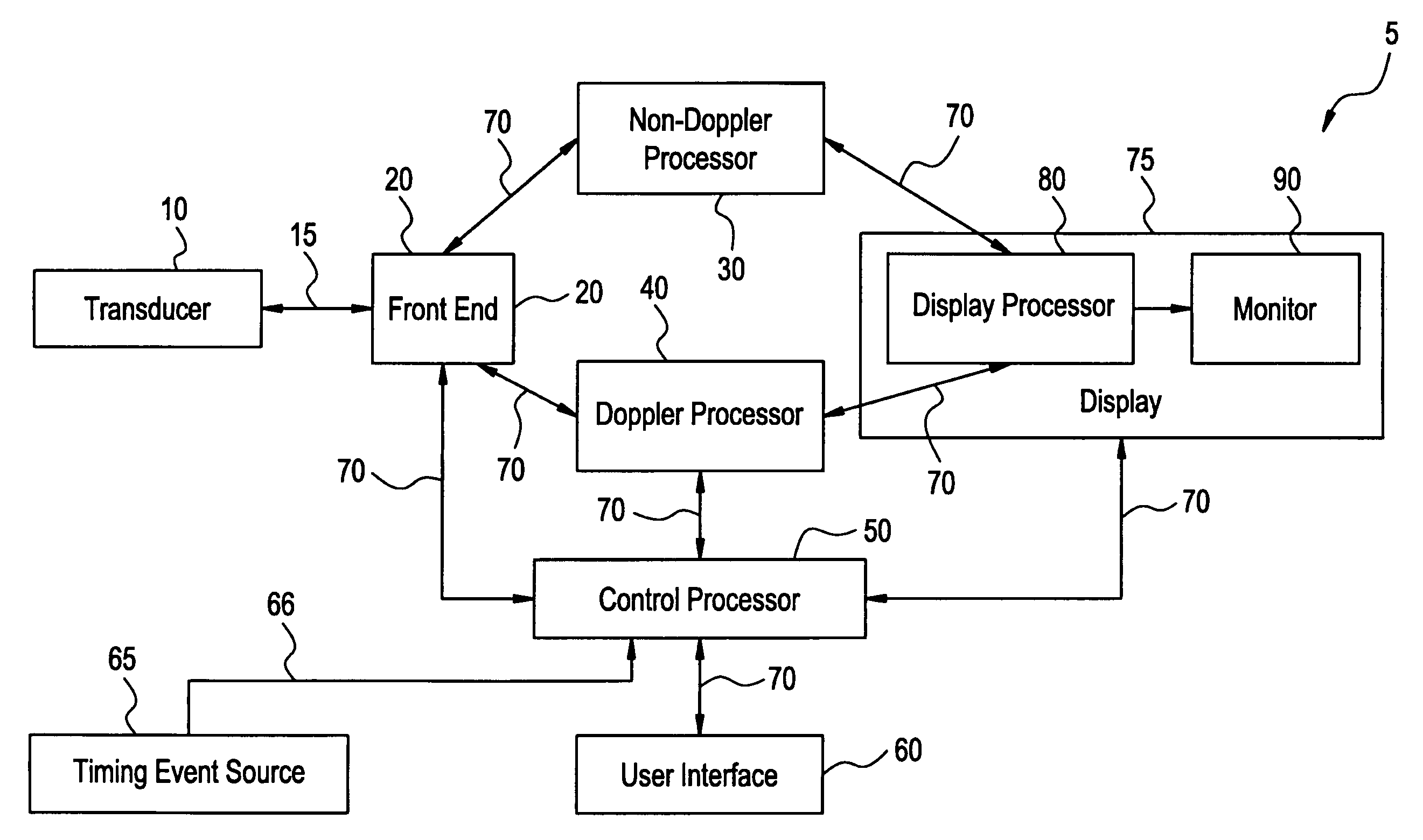
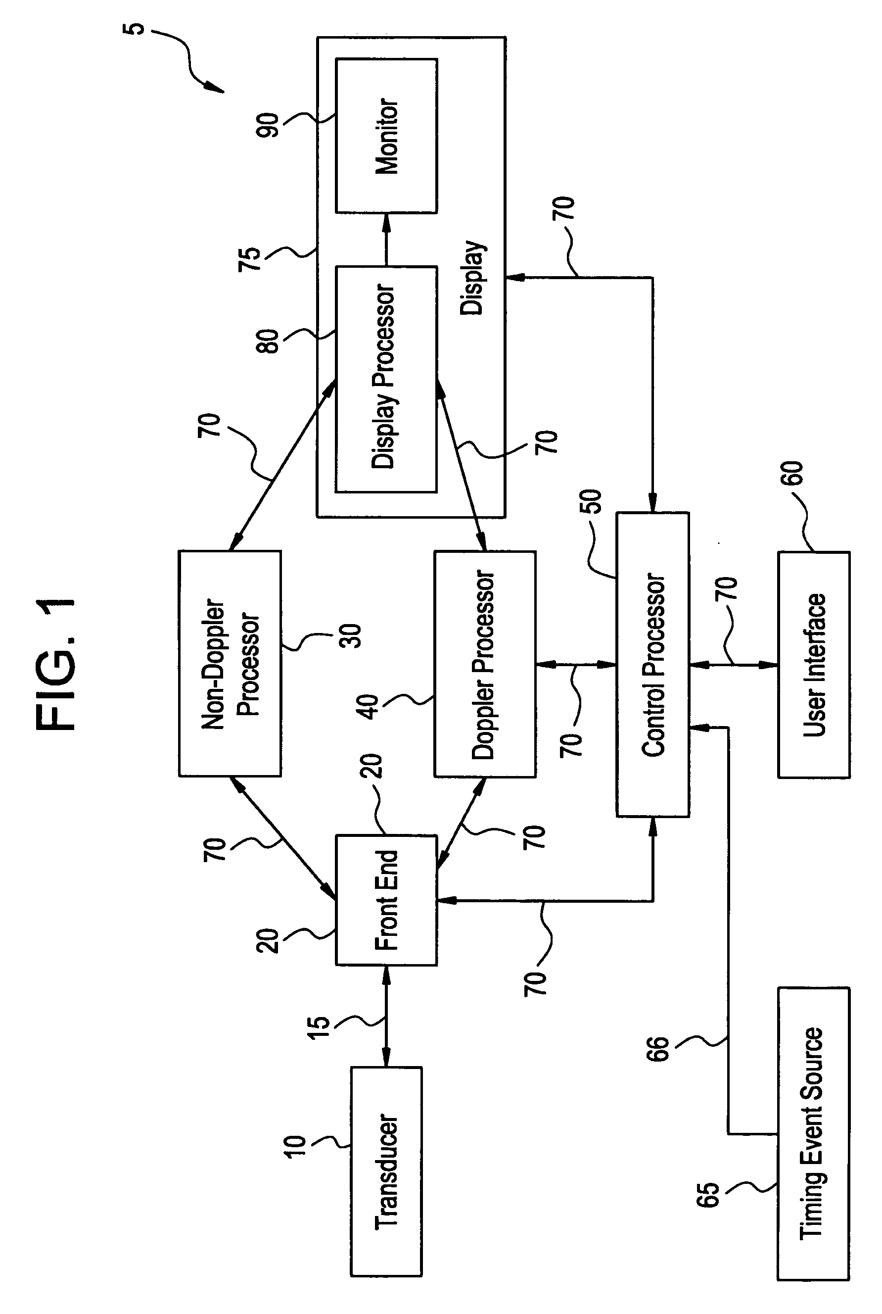
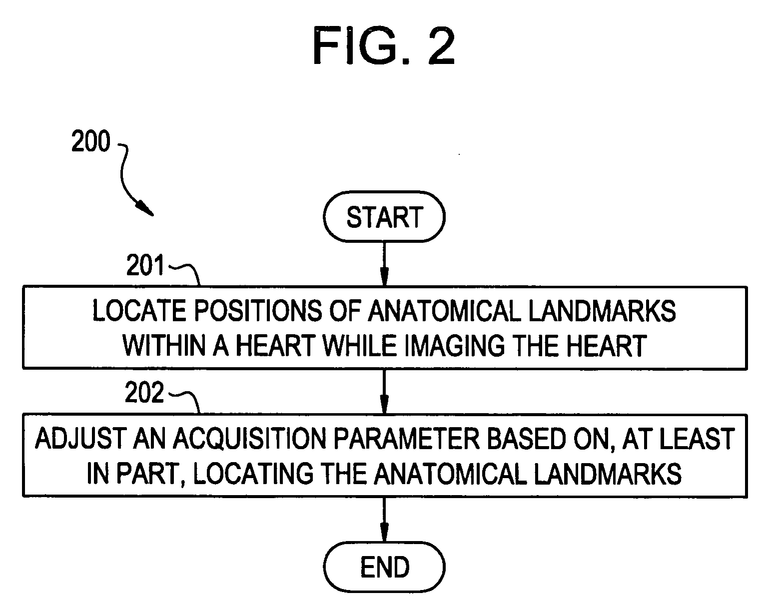
[0023] An embodiment of the present invention enables the automatic adjusting of acquisition parameters, after locating and tracking certain anatomical landmarks of the heart, for subsequent acquisition of certain clinically relevant information. Moving cardiac structure and blood is monitored to accomplish the function. As used herein, structure means non-liquid and non-gas matter, such as cardiac wall tissue for example. An embodiment of the present invention helps establish improved, real-time visualization and assessment of wall function parameters of the heart. The moving structure is characterized by a set of analytic parameter values corresponding to anatomical points within a myocardial segment of the heart. The set of analytic parameter values may comprise, for example, tissue velocity values, time-integrated tissue velocity values, B-mode tissue intensity values, tissue strain rate values, blood flow values, and mitral valve inferred values.

[0024]FIG. 1 depicts a diagram ...


PUM


Abstract

An ultrasound device is disclosed that includes a method and apparatus for generating an image responsive to moving cardiac structure and blood, and for adjusting at least one acquisition parameter based on, at least in part, locating at least one anatomical landmark within a heart. At least one processor, responsive to signals received from the heart, locates anatomical landmarks within the cardiac structure, generate position information of the anatomical landmarks, and adjusts at least one acquisition parameter. The landmarks and acquisition parameters may be displayed to a user of the ultrasound device.

Description

RELATED APPLICATIONS / INCORPORATION BY REFERENCE [0001] This application is related to, and claims benefit of and priority from, Provisional Application No. 60 / 606,078 filed Aug. 31, 2004, titled “OPTIMIZING ULTRASOUND ACQUISITION BASED ON ULTRASOUND-LOCATED LANDMARKS”, the complete subject matter of which is incorporated herein by reference in its entirety. [0002] The complete subject matter of each of the following U.S. patent applications is incorporated by reference herein in their entirety: [0003] U.S. patent application Ser. No. 10 / 248,090 filed on Dec. 17, 2002.[0004] U.S. patent application Ser. No. 10 / 064,032 filed on Jun. 4, 2002. [0005] U.S. patent application Ser. No. 10 / 064,083 filed on Jun. 10, 2002. [0006] U.S. patent application Ser. No. 10 / 064,033 filed on Jun. 4, 2002. [0007] U.S. patent application Ser. No. 10 / 064,084 filed on Jun. 10, 2002. [0008] U.S. patent application Ser. No. 10 / 064,085 filed on Jun. 10, 2002. FEDERALLY SPONSORED RESEARCH OR DEVELOPMENT [0009]...

Claims


Application Information

Patent Timeline
IPC IPC(8): A61B8/02
CPCA61B8/06A61B8/13A61B8/0883A61B8/08
Inventor OLSTAD, BJORN
Owner GENERAL ELECTRIC CO
Why Eureka
Try Eureka