
Roof anchor

a technology for roofs and anchors, applied in the field of roof anchors, can solve the problems of heavy weight, bulky, and difficult to put into place on pitched roofs, and achieve the effect of easy movement and fixed position

Inactive Publication Date: 2006-03-23
ELY ERNIE W
View PDF12 Cites 18 Cited by
  • Summary
  • Abstract
  • Description
  • Claims
  • Application Information

AI Technical Summary

Benefits of technology

[0008] Principal objects of the present invention are to provide a roof anchor that can be secured to a pitched roof as a means for attaching a strap, rope or other line as a tether between the roof anchor and a person climbing on a pitched roof. Further objects are to provide a roof anchor that is easily fixed in position on a pitched roof and that can be easily moved from location to location on the pitched roof and that can be re-anchored, as necessary.
[0009] Another object is to provide a roof anchor that is sufficiently lightweight and small enough that a user can carry several of the roof anchors to be positioned on a roof.
[0010] Still another object of the invention is to provide a roof anchor that can be easily carried up ladders and onto any pitched roof and that can be secured in place and left on the pitched roof as a substantially permanent installation, should that be desired.
[0011] Yet another object of the invention is to provide a roof anchor that is sufficiently low in cost that it can be readily purchased for use by roofers and others climbing on pitched roofs and that can be left on the roof as additional similar roof anchors are used and then, if desired, left in place on the roof, without significantly adversely affecting the appearance of the roof. FEATURES OF THE INVENTION

Problems solved by technology

Generally, the known roof anchors have been heavy, bulky, and difficult to put into place on a pitched roof.
Because of the size, weight, and bulkiness of these known roof anchors it is difficult for users to carry them up ladders and pitched roofs or to move them from location to location and to position and re-position them on the roof.
Also, the known anchors do not always properly fit over different types of ridge lines on roofs having a variety of ridge pitches.

Method used


Image

  • Roof anchor
  • Roof anchor
  • Roof anchor

Examples


Embodiment Construction

[0027] Referring now the Drawings

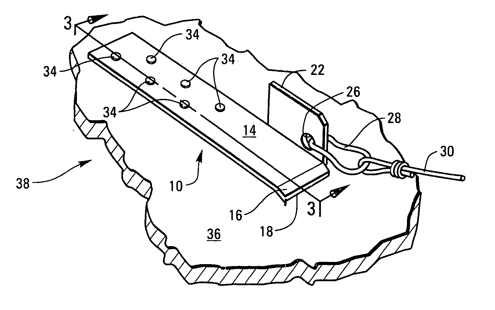
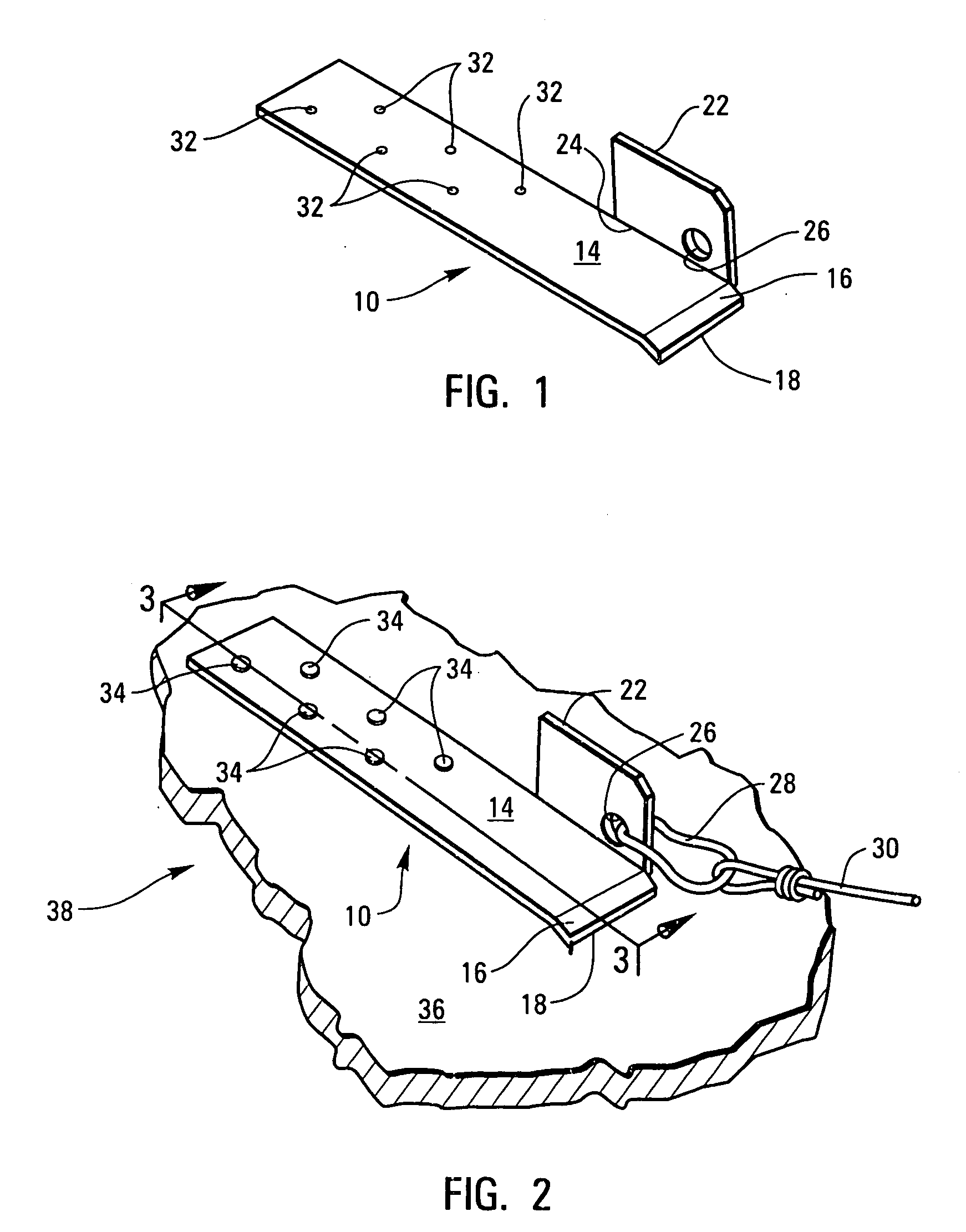
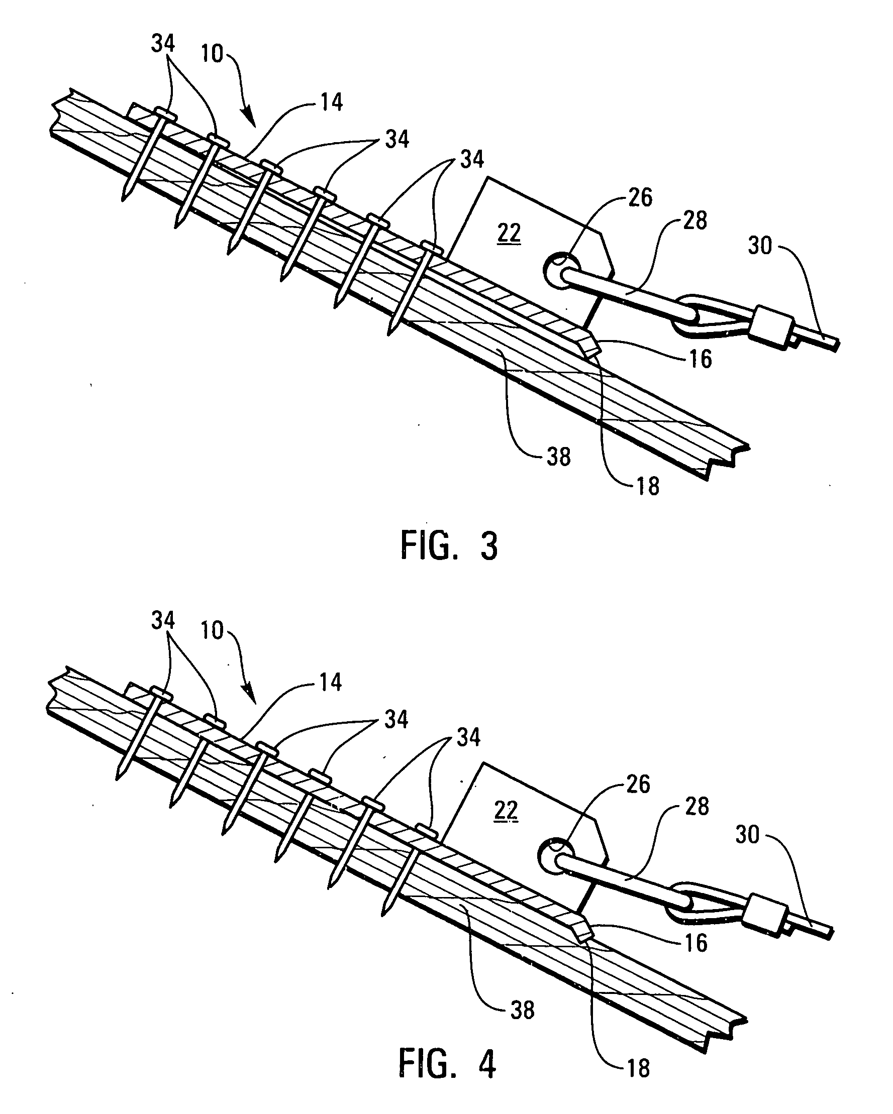
[0028] In the illustrated preferred embodiment of FIGS. 1-6, the roof anchor of the invention is shown generally at 10.

[0029] Roof anchor 10 is made of steel, or the like, and includes an elongate flat bar 14 having a rectangular cross-section and down turned nose end 16. A bottom edge 18 of the down turned nose end 16 provides a sharp edge that will be forced into a roof sheeting, as will be further explained. The remaining portion of the down turned nose end 16 provides an abutment surface, and as will be further explained, prevents downward travel of the roof anchor on a sloped roof, once it has been properly positioned on a roof.

[0030] A connector member 22 is welded or otherwise affixed at 24 to one side of the nose end of the roof anchor 10. A hole 26 through the connector member is spaced slightly above the upper face of the roof anchor and receives a carabiner 28, or other attachment means, for securing a tether line 30.

[0031] A series of...


PUM


Abstract

A roof anchor easily carried to be positioned and re-positioned by persons climbing on pitched roofs and comprising a flat steel bar having a rectangular cross-section, a top surface, a bottom surface, a front end and a rear end with the front end bent to form a nose having a front bottom edge protruding below the bottom surface of the flat plate, a connector member projecting upwardly from the upper surface of the flat bar and forming a hole for attachment of a carabiner and tether line.

Description

CROSS-REFERENCE TO RELATED APPLICATIONS [0001] Not Applicable. STATEMENT REGARDING FEDERALLY SPONSORED RESEARCH OR DEVELOPMENT [0002] Not Applicable. REFERENCE TO MICROFICHE APPENDIX [0003] Not Applicable. BACKGROUND OF THE INVENTION [0004] 1. Field of the Invention [0005] This invention relates to roof anchors to be used to hold persons climbing on pitched building roofs from falling off the roofs. [0006] 2. Description of the Related Art [0007] The need for safety devices for people climbing on pitched roofs of buildings has long been recognized. The safety of roofers, building inspectors, homeowners and others that necessarily must climb on pitched roofs is paramount. Consequently, there have been anchor devices developed in the past that can be secured to the roof and that will support persons climbing on the roof and attached to the anchor devices by straps, ropes, or the like. Generally, the known roof anchors have been heavy, bulky, and difficult to put into place on a pitche...

Claims


Application Information

Patent Timeline
Patent Type & Authority Applications(United States)
IPC IPC(8): E04B1/38
CPCE04G21/3261E04G21/3276
Inventor ELY, ERNIE W.
Owner ELY ERNIE W
Learn More