
Apparatus for forming beam member used for torsion beam for rear wheel suspension of automobile

a technology for rear wheel suspension and apparatus, which is applied in the direction of manufacturing tools, forging/pressing/hammering apparatus, etc., can solve the problems of increasing the frequency of defective products, increasing the number of assembly processes and welding lengths, and deteriorating the productivity of the torsion beam

Inactive Publication Date: 2006-03-23
HWASHIN CO LTD
View PDF10 Cites 41 Cited by
  • Summary
  • Abstract
  • Description
  • Claims
  • Application Information

AI Technical Summary

Benefits of technology

[0014] The present invention has been made to solve the above problems, and it is an object of the present invention to provide an apparatus for forming a beam member used for a torsion beam in a rear wheel suspension system of an automobile, designed to form the beam member having different cross sections at different portions of the beam member and complete symmetry between left and right sides of the beam member by a single process of pressing a cylindrical pipe without distortion or winkling.

Problems solved by technology

However, although such a torsion beam may have sufficient torsion rigidity and bending rigidity via reinforcement of the torsion bar, the number of components for the torsion beam, such as a torsion bar and a reinforcing bar, is increased, and results in increases the number of assembly processes and of welding length, thereby remarkably deteriorating productivity of the torsion beam while increasing the defective product frequency due to difficulty in management of a tolerance upon welding.
Furthermore, the increased number of components also causes reduction in fuel efficiency of the vehicle due to the increased weight of the vehicle.
However, when forming the beam member having different cross sections at different portions by pressing the pipe, as mentioned above, the number of processes for forming the beam member is not regarded as being sufficiently reduced.
Accordingly, in view of the fact that the increase in the number of processes causes not only reduction in productivity, but also increases manufacturing costs, thereby deteriorating price competitiveness of the products, it is necessary to form a beam member with a minimum number of processes.
However, when forming products having different cross sections at different portions of the product, like the beam member used for the torsion beam for the automotive rear suspension system, it is difficult to form a beam member having complete symmetry about the vertical axis of the beam member, since serious distortion or wrinkling of the pipe could occurred at steep change of the shape during deformation when external force is applied from an outer surface of the pipe through the dies.
As such, if complete symmetry between left and right sides of the beam member is not ensured, not only does deterioration of product quality occur due to non-uniform spring rigidity of the product, but misalignment also occurs between wheels and a vehicle frame due to displacement of the trailing arms weld to both sides of the beam member.
Additionally, the torsion beam cannot ensure uniform torsion upon rotation of the vehicle, thereby deteriorating not only performance of a handle, but also durability of the torsion beam, which is caused by strong torsional eccentricity towards one side of the torsion beam.
Accordingly, the method and device of U.S. Pat. No. 6,119,501 cannot be used for forming the products having the different cross sections at the different portions of the product.
Accordingly, not only do installation costs for the devices become very burdensome, but the productivity is also deteriorated due to increase of the number of processes, thereby increasing the manufacturing costs while deteriorating price competitiveness of the products.

Method used


Image

  • Apparatus for forming beam member used for torsion beam for rear wheel suspension of automobile
  • Apparatus for forming beam member used for torsion beam for rear wheel suspension of automobile
  • Apparatus for forming beam member used for torsion beam for rear wheel suspension of automobile

Examples


Embodiment Construction

[0029] Preferred embodiments will now be described in detail with reference to the accompanying drawings.

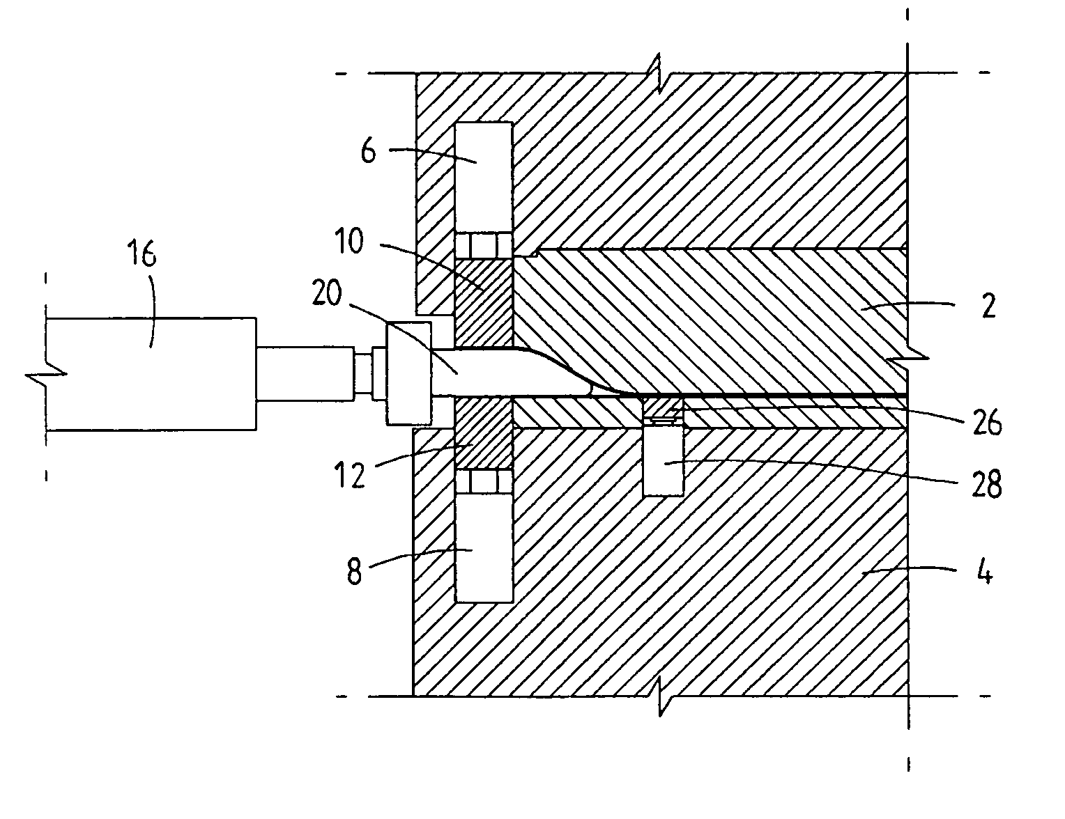
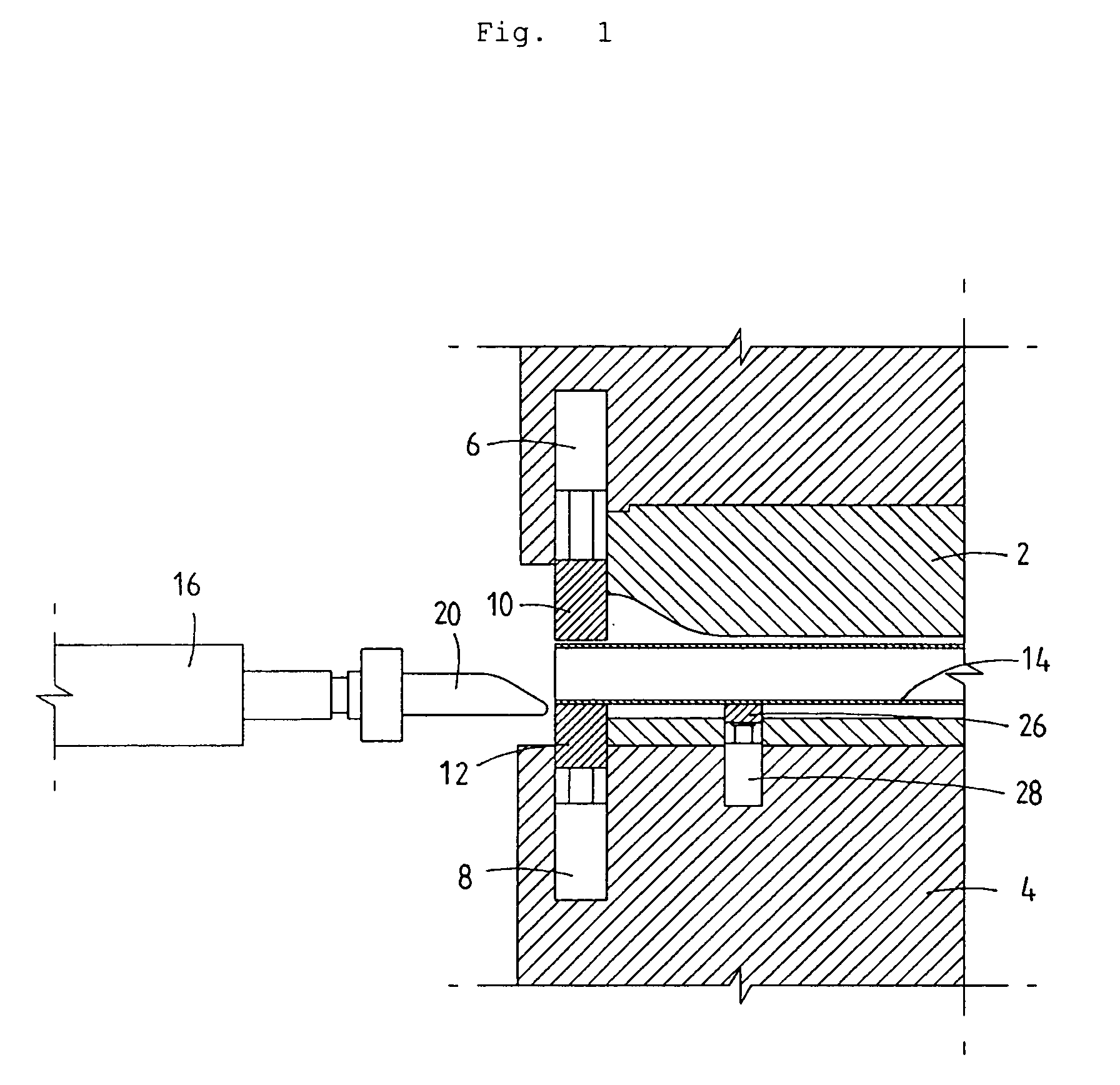
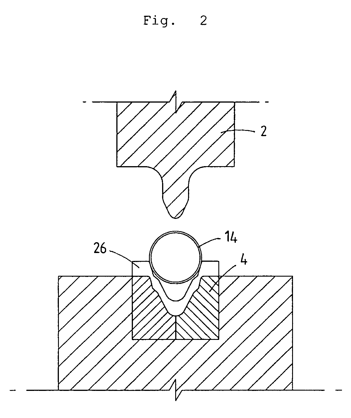
[0030]FIG. 1 is a partial transverse-sectional view illustrating an apparatus according to the present invention before forming operation, and FIG. 3 is a partial transverse-sectional view illustrating the apparatus of the invention upon forming operation. Referring to FIGS. 1 and 3, the apparatus of the invention comprises top and bottom dies 2 and 4 mounted on a die frame connecting the top and bottom dies 2 and 4, upper and lower pad dies 10 and 12 coupled to top and bottom dies 2 and 4 to move up and down in the die frame by means of hydraulic cylinders 6 and 8, and left and right cams 20, which are horizontally inserted into a pipe 14 from both sides of the pipe 14 by a hydraulic cylinder 16.

[0031] The top and bottom dies 2 and 4 have lengths and shapes adapted to form a relatively long U-shaped or V-shaped section 24a at a central portion of a beam member 24, and to form ...


PUM

PropertyMeasurementUnit
Shapeaaaaaaaaaa

Abstract

Disclosed herein is an apparatus for forming a beam member for a torsion beam in a rear wheel suspension system of an automobile. The apparatus comprises top and bottom dies for forming a U-shaped or V-shaped section and an extension section of the beam member, upper and lower pad-dies coupled to top and bottom dies for forming a rectangular section of the beam member before operation of the top and bottom dies, and left and right cams installed at both sides of a pipe so as to be horizontally inserted into the pipe by a hydraulic cylinder for maintaining inner shapes of the extension section and the rectangular section. The cams prevent both distortion and wrinkling from occurring on the rectangular section and the extension section upon operation of the top and bottom dies, thereby allowing the beam member to be formed to have different cross sections at different portions with a complete symmetry by a single process.

Description

BACKGROUND OF THE INVENTION [0001] 1. Field of the Invention [0002] The present invention relates to an apparatus for forming a beam member for a torsion beam in a rear wheel suspension system of an automobile. [0003] 2. Description of the Related Art [0004] A torsion beam for a rear wheel suspension system of a vehicle comprises a beam member, and trailing arms at both sides of the beam member, and acts to maintain a stable posture of the vehicle through torsion of the beam member against a centrifugal force exerted upon rotation of the vehicle. Accordingly, it is necessary for the torsion beam to have strong torsional rigidity and bending rigidity. [0005] Initially, high torsional rigidity and bending rigidity torsion beams were produced in such a manner that, after a steel plate was bent to a beam member having a U-shaped or V-shaped cross section, a reinforcing torsion bar was provided parallel to the beam member inside the beam member, and then welded to the beam member with a ...

Claims


Application Information

Patent Timeline
IPC IPC(8): B21D53/88
CPCB21D41/045B21D53/88B60G21/051B60G2202/136B60G2206/012Y10T29/49622B60G2206/202B60G2206/427B60G2206/8102B60G2206/8103B60G2206/20B21D5/10
Inventor PARK, BYUNG-CHEOL
Owner HWASHIN CO LTD
Learn More