Conveyance system

a technology of conveying system and conveying path, which is applied in the direction of rope railway, charge manipulation, furnaces, etc., can solve the problems of complex structure of conveying path, inability to flexibly change the distance over which workpieces are conveyed by the conventional conveyancing system, and relaying device limit the speed at which workpieces are conveyed

Inactive Publication Date: 2006-03-23
HONDA MOTOR CO LTD +1
View PDF21 Cites 13 Cited by
  • Summary
  • Abstract
  • Description
  • Claims
  • Application Information

AI Technical Summary

Benefits of technology

[0076] Each of conveyance carriages of the conveyance carriage assembly may have two stopping engaging members. Since the stopping engaging members can easily pass through the direction-changing unit, the conveyance carriage assembly is turned in the direction-changing unit.

Problems solved by technology

According to the proposed technology, the conveyance path is complex in structure as an overlap is required between adjacent ones of the conveyors, and it can convey workpieces only in one direction.
This is because the distance over which workpieces are conveyed by the conventional conveyance systems cannot flexibly be changed.
The relaying devices limit the speed at which the workpieces are conveyed, and tend to damage the workpieces being conveyed.
People, forklifts, etc. are prevented from moving in directions transverse to conveyance systems because the conveyance systems present an obstacle to such movement.
If the conveyance system has a large overall length, then they need to take a long detour, and hence the efficiency with which people, forklifts, etc. move in the factory is low.
The vertically conveying elevator structure makes the entire system complex and needs an additional auxiliary process of transferring workpieces, resulting in a reduction in the speed at which the workpieces are conveyed.
However, the technology disclosed in Japanese Patent No. 2536799 requires special actuators known as linear motors, making the conveyance system complicated and expensive.
Since the linear motors are not in general use, parts thereof that are available in distribution are few, giving inconvenience to their maintenance.
If a workpiece to be machined is banged directly on the belt conveyor, then the workpiece is liable to become damaged due to the shock.
Since the workpiece is oriented randomly on the belt conveyor and one surface of the workpiece is held in abutment against the belt conveyor, the transfer device cannot easily grip the workpiece.
If the transfer device fails to grip a desired portion of the workpiece, then it is difficult for the punching device to form the smaller through hole 2 and the larger through hole 4 in desired positions.
However, the jig may possibly fall over.
If a conveyance carriage that has moved at a high speed is abruptly stopped, then a workpiece on the conveyance carriage may be collapsed or damaged due to the shock applied to the conveyance carriage.
Furthermore, the conveyance carriage cannot be moved a distance greater than the distance provided by the chain.
Specifically, the conventional speed control mechanisms or stop control mechanisms for conveyance carriages serve to stop conveyance carriages that move within a limited range, and are unable to stop conveyance carriages that travel in a conveyance assembly which is capable of reversing its direction.
Moreover, since the conveyance carriage cannot quickly be set to travel again, it takes a long period of time to convey workpieces, and hence the efficiency with which to convey workpieces is low.

Method used


Image

  • Conveyance system
  • Conveyance system
  • Conveyance system

Examples


Embodiment Construction

[0115] A conveyance system according to a preferred embodiment of the present invention will be described below with reference to FIGS. 1 through 37.

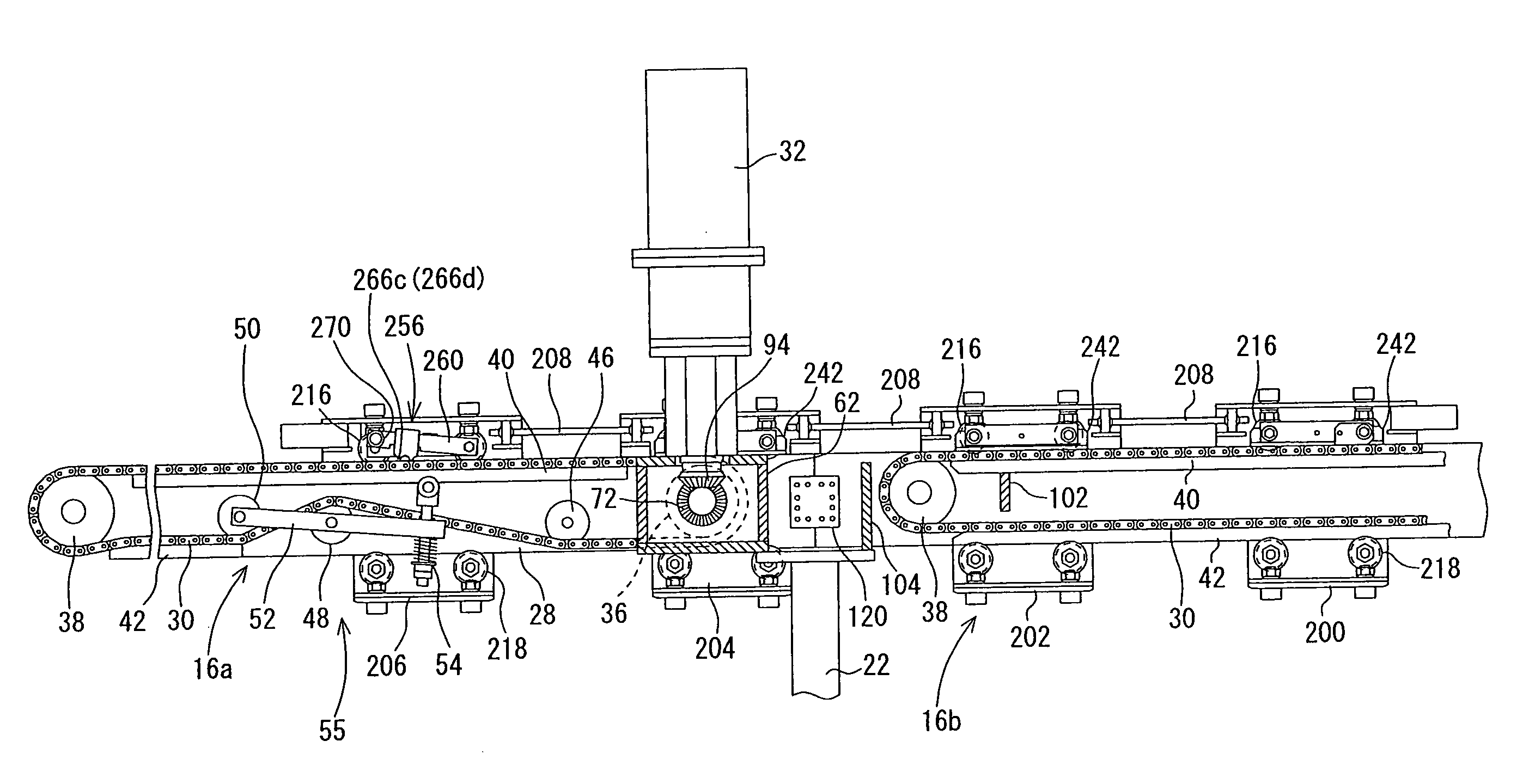
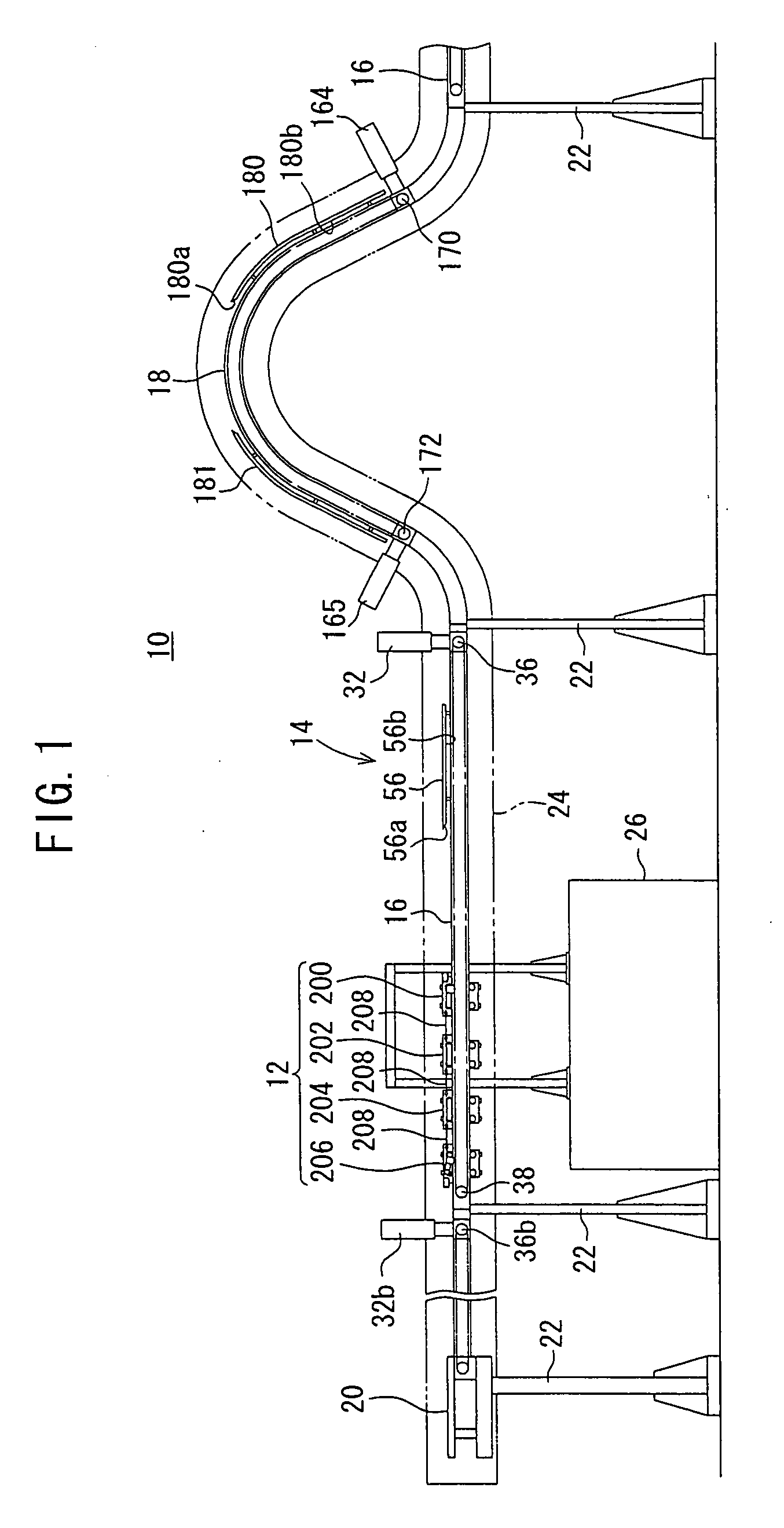
[0116] As shown in FIG. 1, a conveyance system 10 according to the present invention has a joint conveyance carriage assembly 12 capable of conveying a workpiece and a conveyance assembly 14 for conveying the joint conveyance carriage assembly 12, the conveyance assembly 14 providing a conveyance path.

[0117] First, the conveyance assembly 14 will be described below.

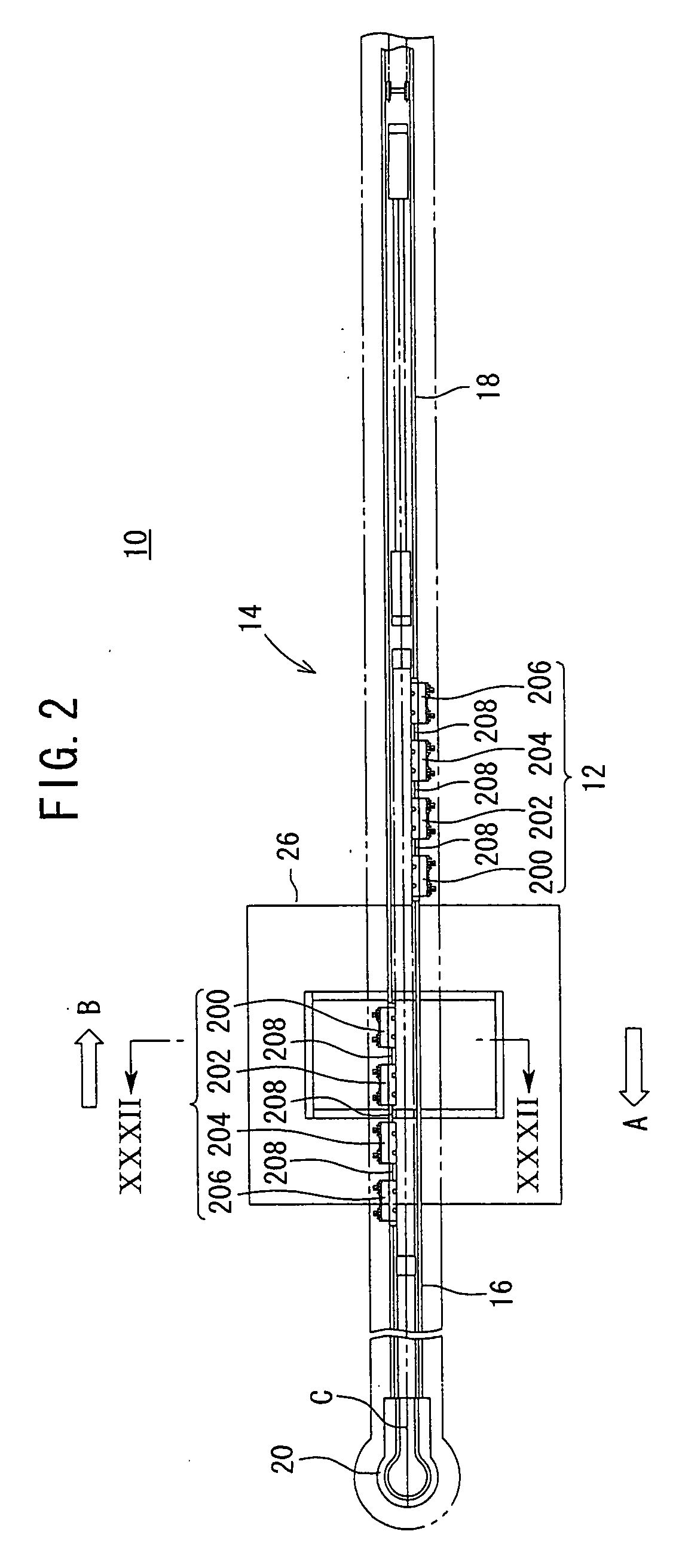
[0118] As shown in FIG. 2, the conveyance assembly 14 has a function to convey the joint conveyance carriage assembly 12 to the right (in the direction indicated by the arrow B) in an upper region in FIG. 2 and to deliver the joint conveyance carriage assembly 12 to the left (in the direction indicated by the arrow A) in a lower region in FIG. 2. The conveyance assembly 14 also has a function to change the direction in which the joint conveyance carriage assembly 12 is del...


PUM


Abstract

A conveyance system, wherein dividable horizontal conveyance units are connected to each other through joint plates and a support post and rails of the horizontal conveyance units are connected to each other without any step and clearance. A joint conveyance carriage assembly is conveyed by a force applied thereto from annular chains of the horizontal conveyance units through chain presser plates. When the rearmost one of the chain presser plates leaves the annular chain of the horizontal conveyance unit, the chain presser plate of the headmost first conveyance carriage reaches the annular chain of the horizontal conveyance unit and the joint conveyance carriage assembly is continuously conveyed.

Description

TECHNICAL FIELD [0001] The present invention relates to a conveyance system for conveying a workpiece with a conveyance carriage, and more particularly to a conveyance system which is capable of increasing or reducing the distance over which a workpiece is to be conveyed depending on the layout in a site which incorporates the conveyance system. BACKGROUND ART [0002] If a factory has a plurality of processes for machining workpieces, machining facilities corresponding to the respective processes are often arranged in line. Conveyance systems having linear conveyance paths extending along the machining facilities are used to transfer workpieces between the machining facilities. [0003] One conveyance system for conveying workpieces along a linear path is a conveyor system, for example. [0004] There has been proposed a technology for forming a conveyance path by interconnecting a plurality of conveyors (for example, see Japanese Laid-Open Patent Publication No. 55-66414). According to ...

Claims


Application Information

Patent Timeline
Patent Type & Authority Applications(United States)
IPC IPC(8): B65G35/06B65G35/08
CPCB65G35/08B65G35/06B65G35/00B65G47/61B65G1/0457B65G1/065B65G47/1421
Inventor IWAI, YOSHIHARUNONAKA, MASANORI
Owner HONDA MOTOR CO LTD
Why Eureka
Try Eureka