Six-bar linkage positioning mechanism
a positioning mechanism and six-bar technology, applied in the direction of mechanical control devices, process and machine control, instruments, etc., can solve the problems of inability to estimate the safety of the motion mechanism, inability to accurately control the motion path,
- Summary
- Abstract
- Description
- Claims
- Application Information
AI Technical Summary
Benefits of technology
Problems solved by technology
Method used
Image
Examples
first embodiment
[0060] Referring to FIG. 8 through FIG. 12, a six-bar linkage positioning mechanism is shown constructed according to the present invention and mounted inside a clean container 1. The clean container 1 comprises a base 12, and a cover shell 11 covered on the base 12. The base 12 holds a cassette 13 at the top. The cassette 13 comprises a plurality of insertion slots 130 transversely (horizontally) arranged at different elevations for carrying a plurality of workpieces 131. According to this embodiment, the workpieces 131 are wafers.
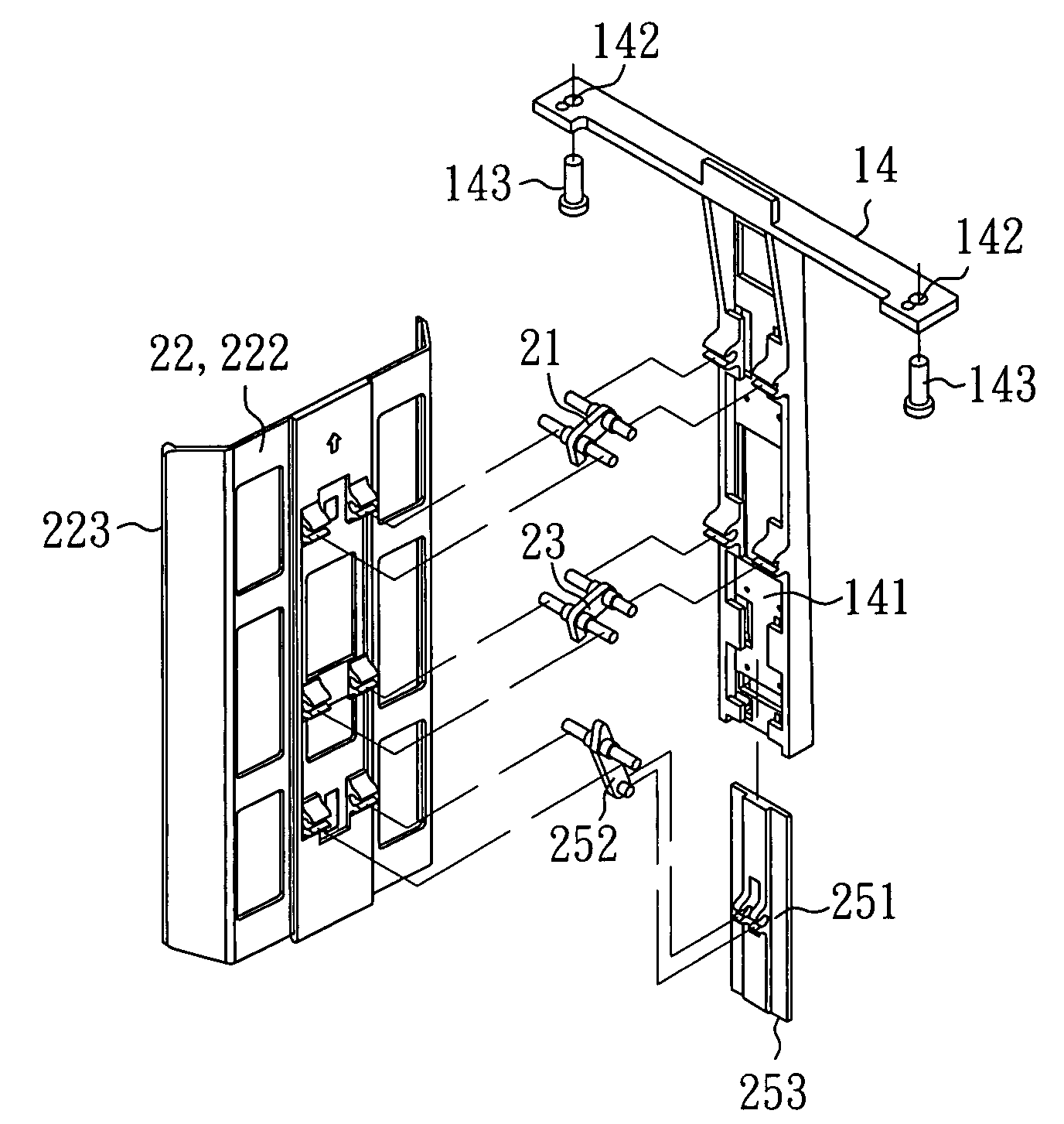
[0061] Further, the aforesaid six-bar linkage positioning mechanism comprises a locating member 14, a four-bar linkage 2, and a driving module 25. The locating member 14 is fixedly fastened to an inside wall 111 of the cover shell 11 of the clean container 1. The locating member 14 has a vertically extended sliding way 141 and two mounting holes 142 respectively formed in the two distal ends of the top thereof and respectively fixedly fastened to the insi...
third embodiment
[0068]FIG. 18˜FIG. 22 show a six-bar linkage positioning mechanism constructed according to the present invention.
[0069] According to this embodiment, the six-bar linkage positioning mechanism is mounted inside a clean container 5, which comprises a base 52 and a cover shell 51 covered on the base 52. The base 52 holds a cassette 53 at the top. The cassette 53 comprises a plurality of insertion slots 530 transversely (horizontally) arranged at different elevations for carrying a plurality of workpieces 531. According to this embodiment, the workpieces 531 are wafers.
[0070] According to this embodiment, the six-bar linkage positioning mechanism comprises a locating member 55, a parallel four-bar linkage 4, and a supporting link 45. The locating member 55 is fixedly fastened to an inside wall 511 of the cover shell 51 of the clean container 5. The locating member 55 has a vertically extended sliding way 551 vertically disposed on the middle, and two mounting holes 552 respectively fo...
fifth embodiment
[0077]FIG. 28˜FIG. 32 show a six-bar linkage positioning mechanism constructed according to the present invention. According to this embodiment, the six-bar linkage positioning mechanism comprises a first link 71, a second link 72, a third link 73, a fourth link 74, a fifth link 75, and a sixth link 76. The sixth link 76 is axially slidably slid along the first link 71. The fourth link 74 has three pivot points 741, 742 and 743 respectively pivoted to the third link 73, the fifth link 75 and the sixth link 76. The fifth link 75 is pivotally pivoted between the second link 72 and the fourth link 74.
[0078] When the sixth link 76 (the slide) is moved, it will carry the third link 73 (the retainer) to move workpieces 771 transversely (horizontally) in the cassette 77 by means of contact at a point. Therefore, the six-bar linkage positioning mechanism is constructed to have one degree of freedom so that the third link 73 can be moved transversely (horizontally) to push every workpiece 77...
PUM
 Abstract
Description
Claims
Application Information
 - R&D
- Intellectual Property
- Life Sciences
- Materials
- Tech Scout
- Unparalleled Data Quality
- Higher Quality Content
- 60% Fewer Hallucinations
Browse by: Latest US Patents, China's latest patents, Technical Efficacy Thesaurus, Application Domain, Technology Topic, Popular Technical Reports.
© 2025 PatSnap. All rights reserved.Legal|Privacy policy|Modern Slavery Act Transparency Statement|Sitemap|About US| Contact US: help@patsnap.com


