Filter device

a filter device and filter liquid technology, applied in the field of filter devices, can solve the problems of difficult adhesion of solid substances to the filter elements, and achieve the effect of enhancing the effect of compressed air flow on the filter liquid and minimising energy requirements

Inactive Publication Date: 2006-03-23
UTISOL TECH AG
View PDF3 Cites 18 Cited by
  • Summary
  • Abstract
  • Description
  • Claims
  • Application Information

AI Technical Summary

Benefits of technology

[0014] By the compressed air flowing out—and also by the suction extraction of filtrate from the filters—through the at least one aperture of the hollow space, respectively, between the filter plates located underneath the hollow space, filter liquid is sucked in. The mixture of air and liquid produced by this flows upwards between the filter elements having a space between one another. Through the rotational movement a sequential cleaning of the filter modules takes place. As a result of this, an adhesion of solid substances to the filter elements is rendered more difficult, or prevente

Problems solved by technology

This device, for the purpose of forming a mixture of gas and liquid, is capable of being impinged on with compressed gas and is arranged in such a manner that in the li

Method used


Image

  • Filter device
  • Filter device
  • Filter device

Examples


Embodiment Construction

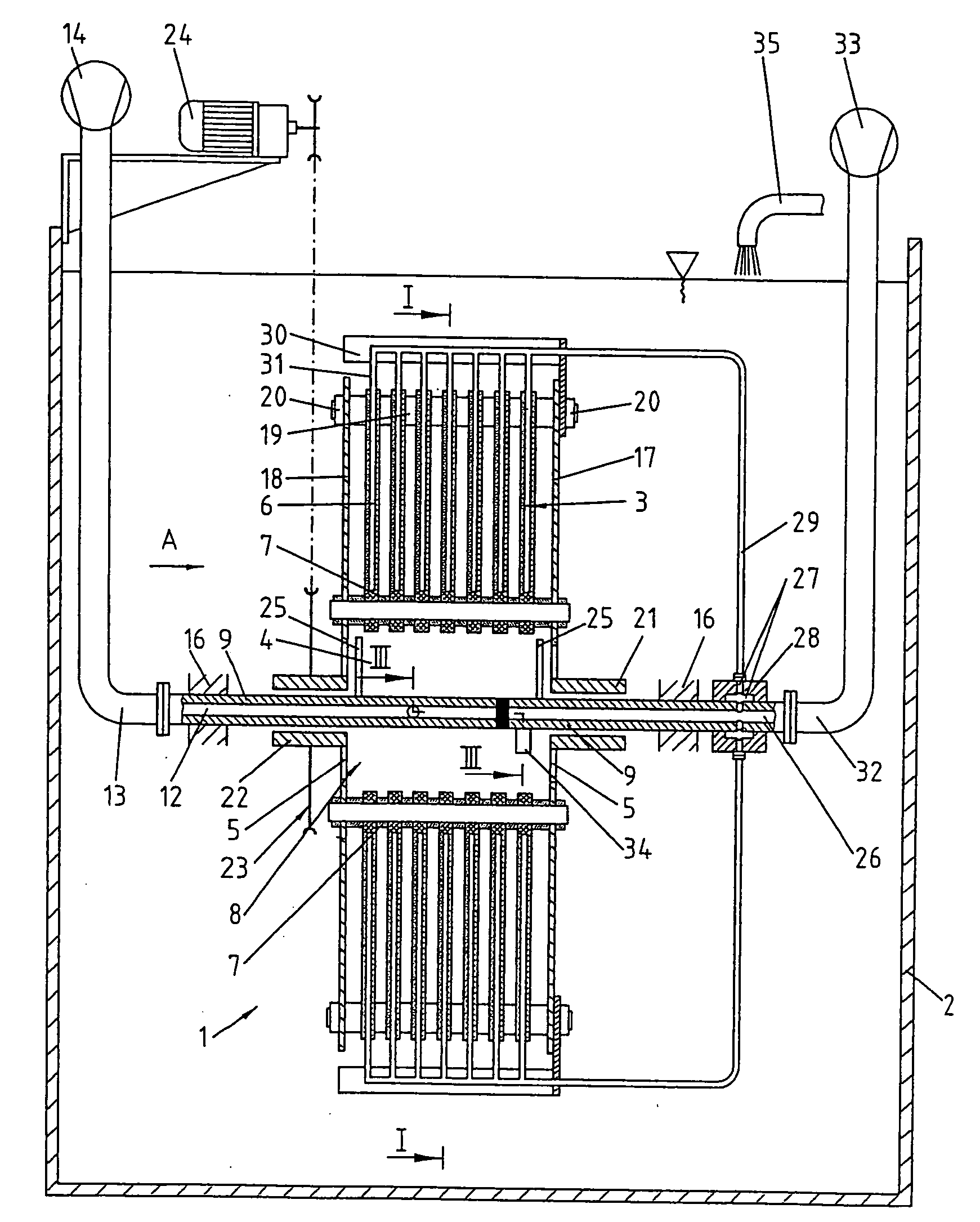
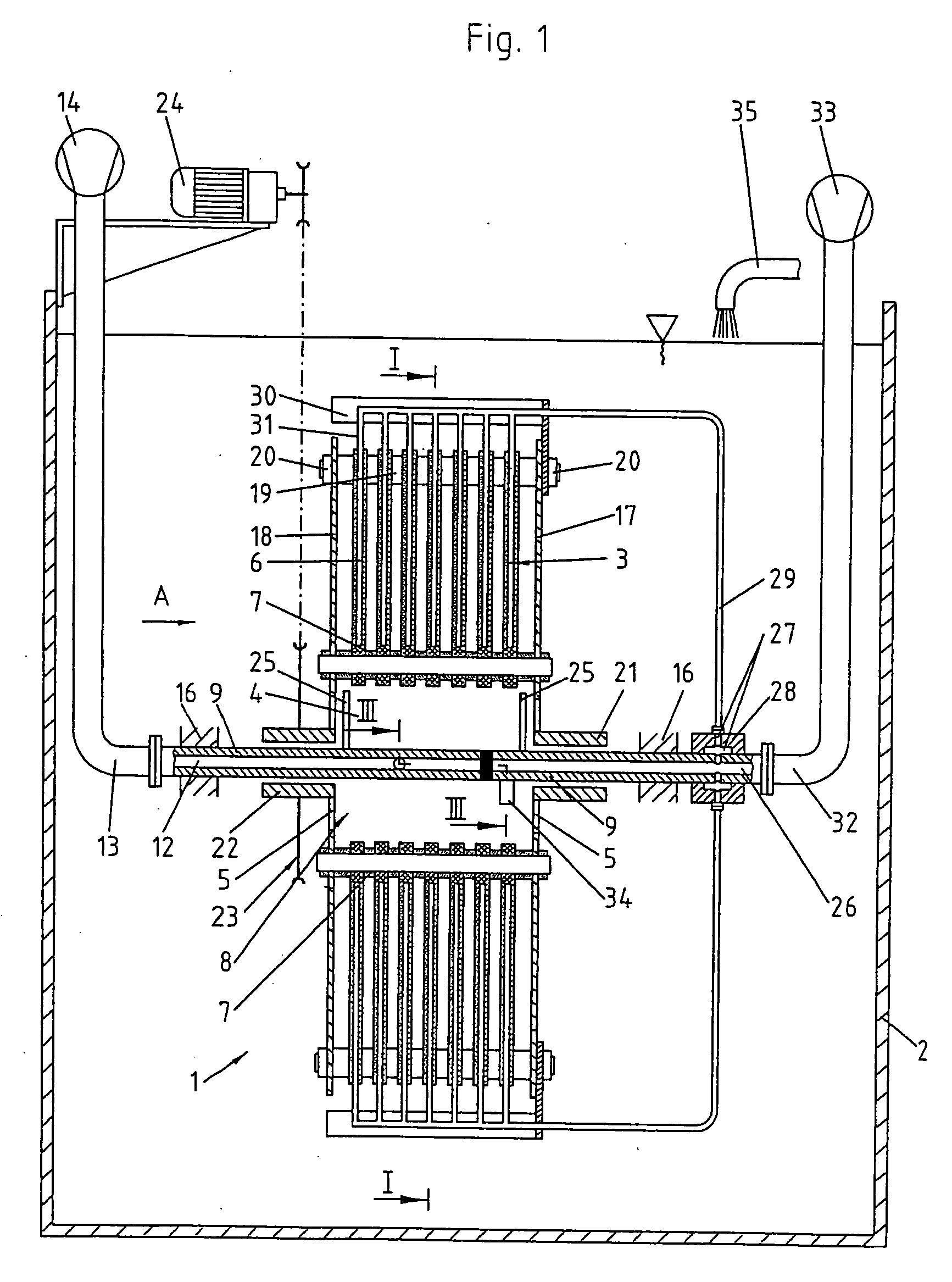
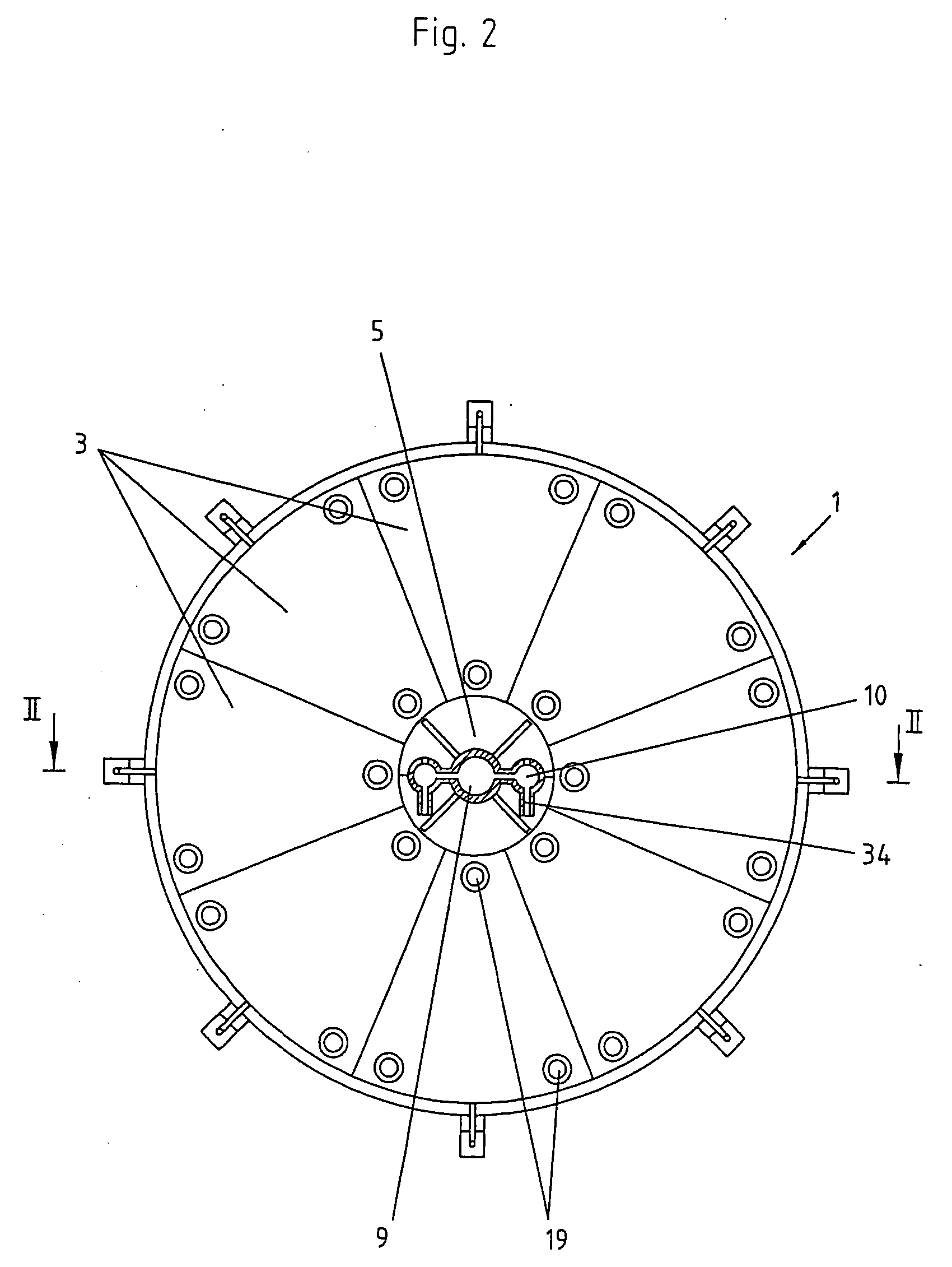
[0025] The FIGS. 1 to 3 illustrate a first preferred embodiment of the invention: The filter device 1 is accommodated rotatably in a container 2 filled with filter liquid. It comprises several filter modules 3. The individual filter modules 3 combine to form plate-like, at the periphery e.g. circular or polygon-shaped filter elements 6. The individual filter elements 6 are joined together with a space between them of, e.g., 4 to 8 mm. The filter modules 3 combined to form the filter elements 6 consist, for example, of several essentially parallel filter plates (not illustrated), which as such are already known. The filtrate is drained off through the filter plates, which are provided with filters on both sides. By means of spacer plates 7, it is possible to adjust the space between the filter elements 6. In the hollow space 4, an aeration device 8 is arranged horizontally. The aeration device 8 consists of hollow bodies 10 arranged parallel to a hollow shaft 9, which extend over the...


PUM

PropertyMeasurementUnit
Flow rateaaaaaaaaaa

Abstract

The filter device is utilized for the separation of undissolved solid substances from liquids, in particular in the fields of waste water purification and water treatment. The filter device is arranged in a container as capable of rotation (2) and surrounded by the liquid to be filtered. The filter device (1) consists of several filter elements (6) with a space between one another, which are combined to form a rotating filter. The filtrate is drained away at the periphery of the filter elements (6). Solid substances are prevented from adhering to the filter elements (6) during the filtering process. The rotating filter comprises a hollow space in the center and an aeration device (8) is arranged in the hollow space, around which the filter device rotates. The filters are continuously cleaned by the mixture of air and liquid flowing through during the filtering process.

Description

BACKGROUND OF THE INVENTION [0001] 1. Field of the Invention [0002] The invention is related to a filter device, which serves for the separation of undissolved substances from liquids, and which is employed in particular in the fields of waste water purification and water treatment. Especially in biological waste water purification, with these filter devices the activated sludge is separated from the treated waste water. [0003] 2. Description of the Related Art [0004] Known filter devices comprise filtering elements with a space between one another, which are combined into filter modules and are arranged in a circular—or polygon-shaped design to be rotatable in a container containing the filter liquid. Serving as filtering elements are either filter plates, which comprise filters on both sides or else porous hollow fibres. The filtrate is suction extracted through conduits at the periphery of the filtering elements. As the filtering time progresses, the solid substances retained fro...

Claims


Application Information

Patent Timeline
IPC IPC(8): B01D33/00B01D33/21
CPCB01D33/21B01D2201/087B01D33/68
Inventor HARMS, EBERHARDGRIGO, MARK
Owner UTISOL TECH AG
Why Eureka
Try Eureka