Optical discharge apparatus and image forming apparatus containing the same

a technology of optical discharge apparatus and image forming apparatus, which is applied in the direction of discharge tube/lamp details, electrographic process, instruments, etc., can solve the problems of inability to achieve a consistent degree of illumination, inability to achieve sufficient cost reduction, and more light illumination, so as to reduce the size of such an image forming apparatus, reduce the size of the image forming portion, and simple configuration

Active Publication Date: 2006-03-23
SHARP KK
View PDF13 Cites 22 Cited by
  • Summary
  • Abstract
  • Description
  • Claims
  • Application Information

AI Technical Summary

Benefits of technology

[0044] As described above, with the image forming apparatus of the present invention, an optical discharge apparatus having the aforementioned characteristics is provided on each photoreceptor of the image forming portions that are lined up in tandem. In order to reduce the size of such an image forming apparatus, it is necessary to reduce the size of the image forming portions, and thus it is preferable to apply a device that is small as the photo charge removal device of the image forming portions. The optical discharge apparatus having the aforementioned characteristics has a simple configurati

Problems solved by technology

However, with this configuration, since the number of LED ships 502 is large, it has been difficult to achieve sufficient reductions in cost.
Thus it has not been possible to achieve a consistent degree of illumination.
However, with the configurations described in aforementioned patent references, there still remains the problem that, of those regions of the photosensitive drum that are illuminated by the light fr

Method used


Image

  • Optical discharge apparatus and image forming apparatus containing the same
  • Optical discharge apparatus and image forming apparatus containing the same
  • Optical discharge apparatus and image forming apparatus containing the same

Examples


embodiment 1

Image Forming Apparatus

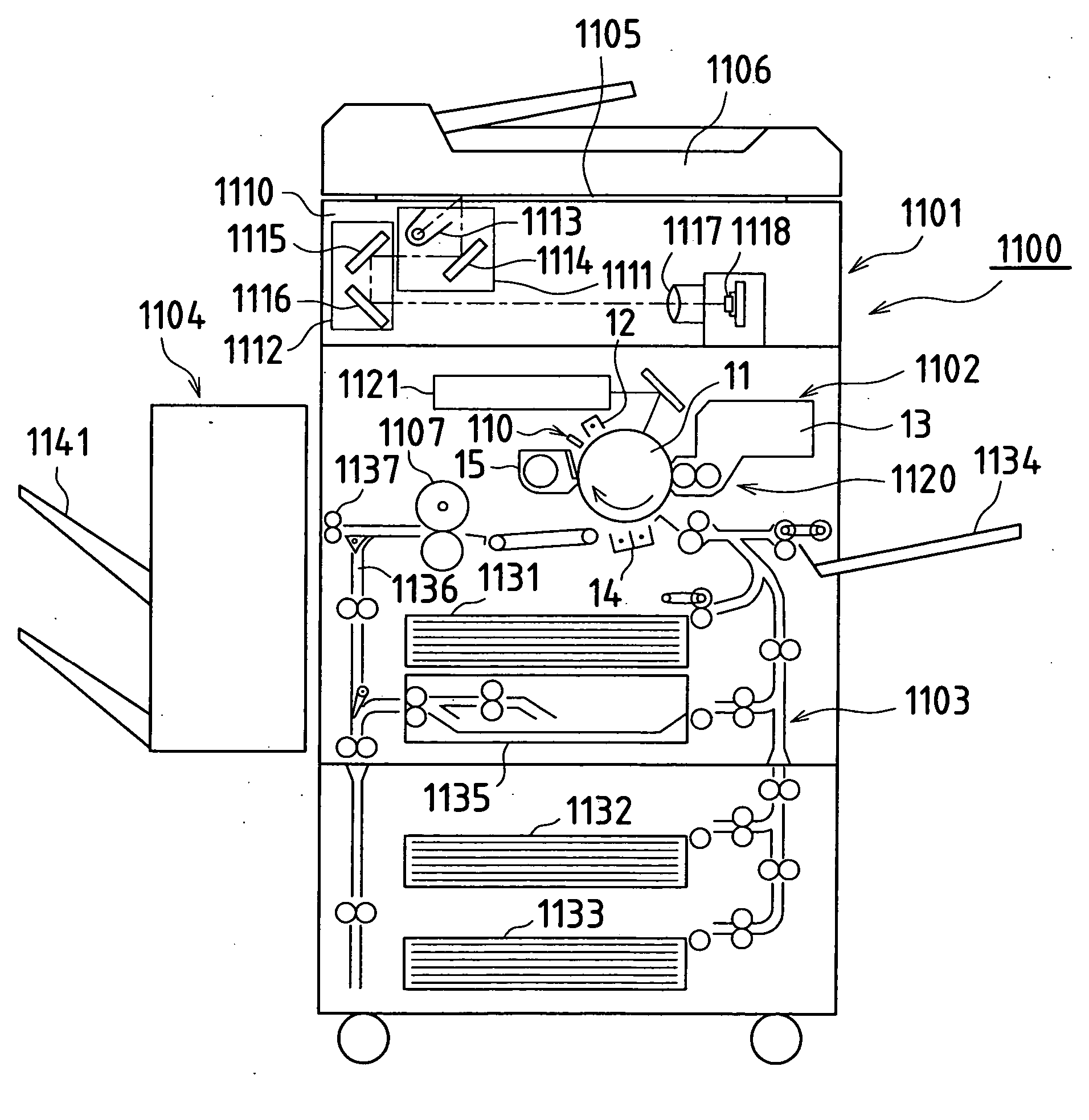
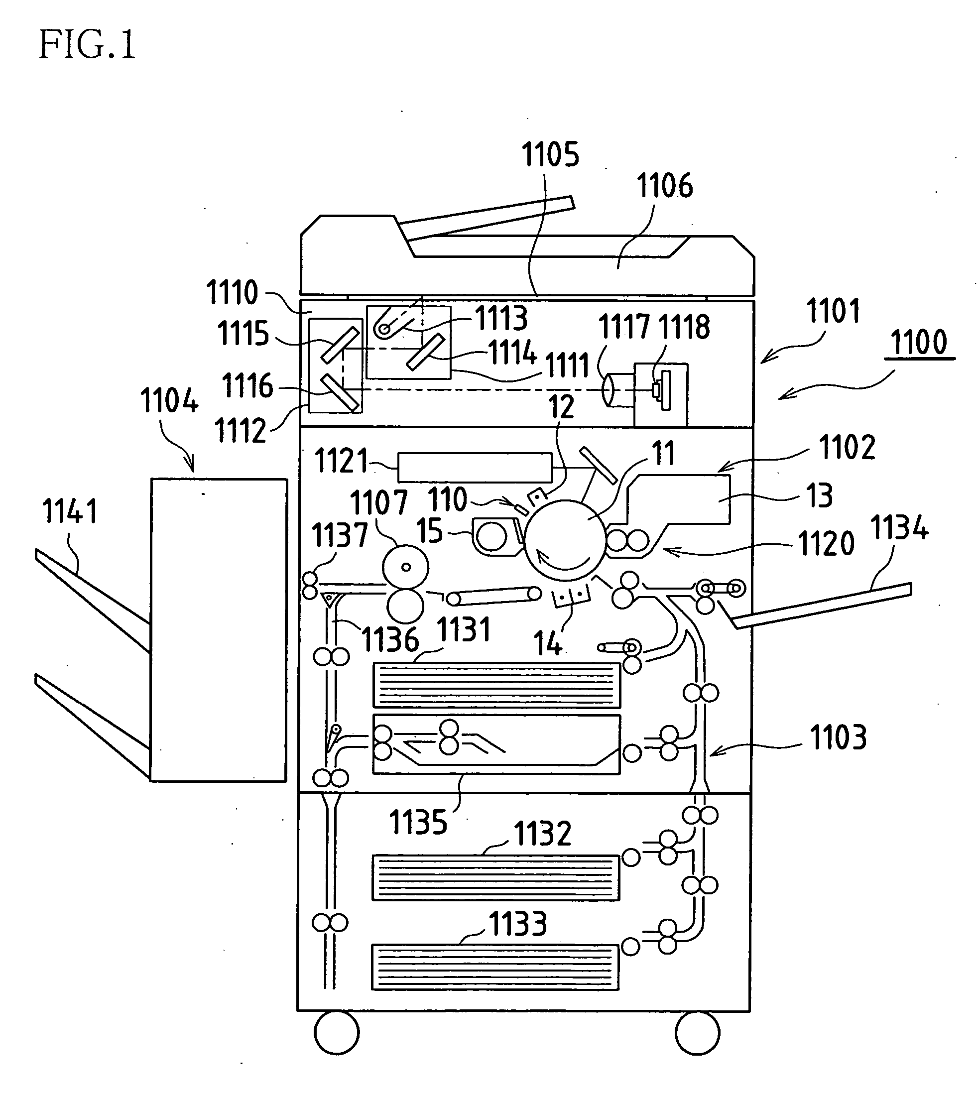
[0077]FIG. 1 is a view showing an image forming apparatus according to Embodiment 1 of the present invention.

[0078] An image forming apparatus 1100 of the present example is a digital combined machine that is capable of operating as a facsimile, a copier, and a printer, and it is provided with an image reading portion 1101, an image forming portion 1102, a paper feed portion 1103 and a post-processing device 1104.

[0079] The image forming portion 1101 is provided as an image input device of the image forming apparatus 1100 for the purpose of reading images from a document, or the like. In addition to a document platen 1105 made of transparent glass, the image forming portion 1101 is provided with a reverse-side automated document feeder (hereinafter referred to as an “RADF”) and an optical unit 1110.

[0080] The image reading portion 1101 sequentially reads in, page by page, images from a document that is placed on the document platen 1105. The RADF 1106 tra...

embodiment 2

[0104] An optical discharge apparatus according to Embodiment 2 of the present invention is shown in FIG. 6A and FIG. 6B.

[0105] An optical discharge apparatus 1210 is provided with a light guiding member 1212 that is arranged opposite the photosensitive drum 11 (see FIG. 3), and an LED lamp 111 that irradiates light onto a light incident face 1212a of the light guiding member 1212.

[0106] A reverse side 1212d of the light guiding member 1212 is substantially an inclined face, and a diffusing reflecting face (prism face) 1212c is formed on the inclined face for reflecting the light from the LED lamp 111 in the direction of the photosensitive drum 11.

[0107] The diffusing reflecting face 1212c of the light guiding member 1212 is formed such that the height H to a light emitting surface 1212b, and a width W of the diffusing reflecting face 1212c (the length in a direction perpendicular to the axial direction of the photosensitive drum 11) decrease at a constant rate toward a rear end ...

embodiment 3

[0112] An optical discharge apparatus according to Embodiment 3 of the present invention is shown in FIG. 8.

[0113] An optical discharge apparatus 1310 is a modified example of the optical discharge apparatus in FIG. 4, wherein as well as providing a light guiding path portion 1312f that has a folded structure, reflecting faces (total reflecting faces) 1312g and 1312h for bending and guiding the light that is incident on a light incident face 1312a (the light emitted by the LED lamp 111) to the diffusing reflecting face 1312c, are formed between the light guiding path 1312f and the diffusing reflecting face 1312c. It should be noted that the height H of the diffusing reflecting face 1312c of a light guiding member 1312 in this example, to the light emitting face 1312b, and the width W of the diffusing reflecting face 1312c, are the same as those of the light guiding member 112 shown in FIG. 4.

[0114] Furthermore, as shown in the enlargement in FIG. 9, a steep inclined face 1312i is ...


PUM


Abstract

In an optical discharge apparatus used in an electrographic image forming apparatus, by forming, on a light guiding member, a diffusing reflecting face for reflecting light from an LED lamp towards a photosensitive drum, and by supplementing the amount of light by altering the height of the diffusing reflecting face to the light emitting face and the width of the diffusing reflecting face in accordance with their distance from the light source, the light intensity distribution of the irradiating light that is irradiated onto the photosensitive drum is made uniform. Furthermore, since light that leaks from the diffusing reflecting face is reflected by a reflecting film that is pasted onto an upper face in the vicinity of a rear end portion of the light guiding member, and returned to the interior of the light guiding member, the amount of light that is irradiated from the light emitting face in the vicinity of the rear end portion of the light guiding member increases, and thus it is possible to further increase the uniformity of the light intensity distribution of the irradiating light. Furthermore, an optical discharge apparatus used in an electrographic image forming apparatus is provided with a light guiding member that is arranged facing the photosensitive drum of the image forming apparatus, and an LED lamp for irradiating the light onto the light incident face of the light guiding member. A diffusing reflecting face for reflecting the light from the LED lamp toward the photosensitive drum is formed on the light guiding member. The rear end face of the light guiding member is an optically transparent face, and the amount of irradiating light that is irradiated onto the photosensitive drum from the vicinity of the rear end portion of the light guiding member increases by forming a reflecting face behind the rear end face of the light guiding member.

Description

BACKGROUND OF THE INVENTION [0001] This application claims priority under 35 U.S.C. § 119(a) on Patent Application No. 2004-275713 filed in Japan on Sep. 22, 2004, and on Patent Application No. 2004-299329, filed in Japan on Oct. 13, 2004, the entire contents of which are hereby incorporated by reference. [0002] The present invention relates to optical discharge apparatuses for removing residual electric charges on photosensitive bodies by irradiating light, and to image forming apparatuses such as copier machines provided with same, in electrographic image forming processes. [0003] As electrographic image forming apparatuses such as copier machines, there exist monochrome image forming apparatuses for forming black and white images, and color image forming apparatuses for forming color images. For color image forming apparatuses, there are multi-rotational image forming apparatuses for sequentially forming a toner image of composite colors onto a single photoreceptor via toner imag...

Claims


Application Information

Patent Timeline
IPC IPC(8): H01J5/16H01L27/00H01J3/14
CPCG03G21/08
Inventor NISHIMURA, YASUHIROINO, TOSHIAKITOKUYAMA, MITSURUMORIMOTO, KIYOFUMIKITAGAWA, TAKASHI
Owner SHARP KK
Why Eureka
Try Eureka