Image processing apparatus
- Summary
- Abstract
- Description
- Claims
- Application Information
AI Technical Summary
Problems solved by technology
Method used
Image

Examples
first embodiment
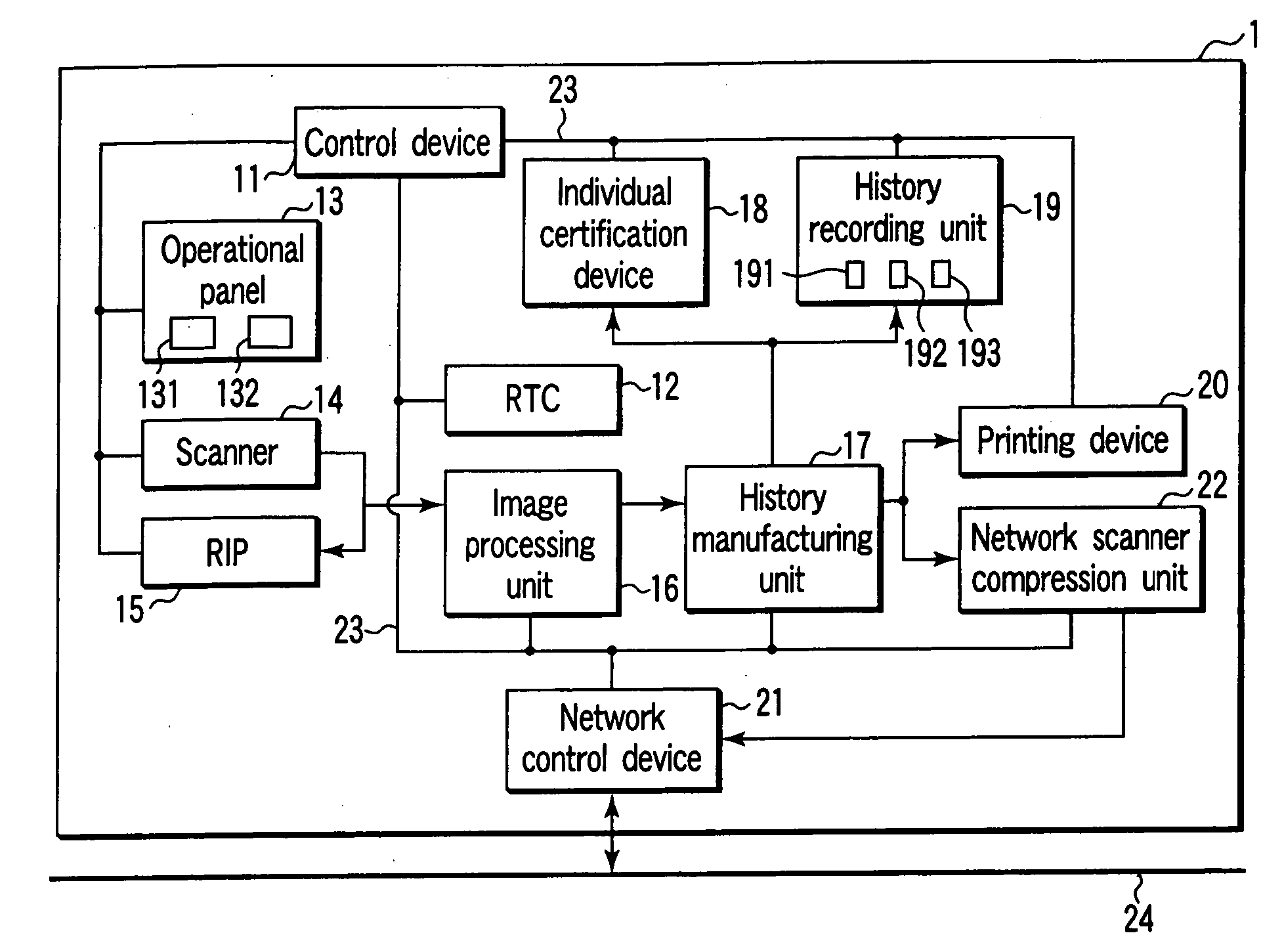
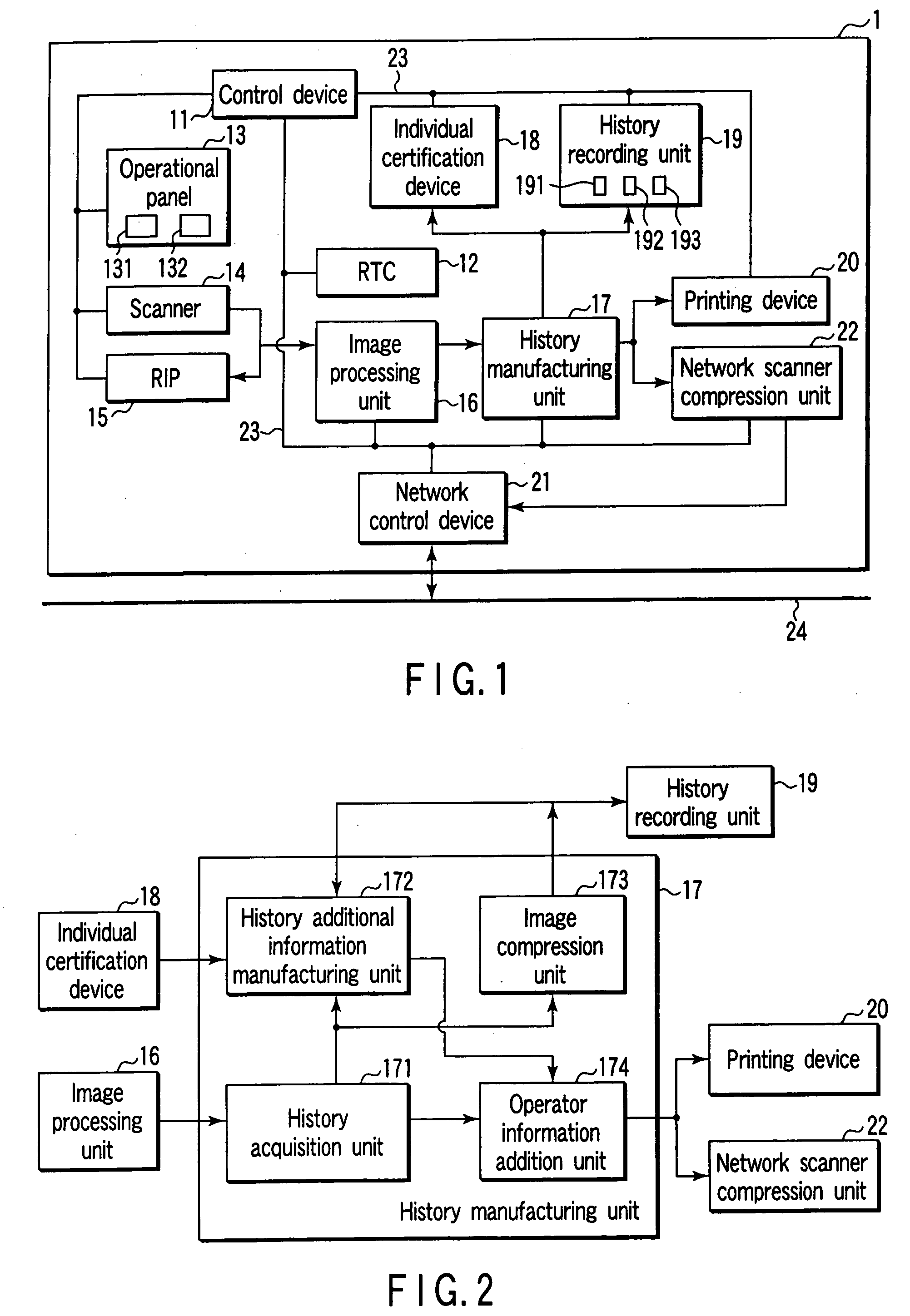
[0030]FIG. 1 is a schematic diagram showing an inner structure of an MFP 1. The MFP 1 is configured by a control device 11, a real time clock (RLC) 12, an operational panel 13, a scanner 14, a raster image processor (RIP) 15, an image processing unit 16, a history manufacturing unit 17, an individual certification device 18, a history recording unit 19, a printing device 20, a network control device 21, and a network scanner compression unit 22. The control device 11, the RTC 12, the operational panel 13, the scanner 14, the RIP 15, the image processing unit 16, the history manufacturing unit 17, the individual certification device 18, the history recording unit 19, the printing device 20, the network control device 21, and the network scanner compression unit 22 are connected each other via a bus line 23.
[0031] The control device 11 is configured by a CPU, a ROM, a RAM and the like. The control device 11 generally controls the entire MFP 1. The RTC 12 generates current time inform...
second embodiment
[0055] Next, a second embodiment of the present invention will be described below. The same numeral references are given to the same parts as the above-described first embodiment and its detailed explanation is herein omitted.
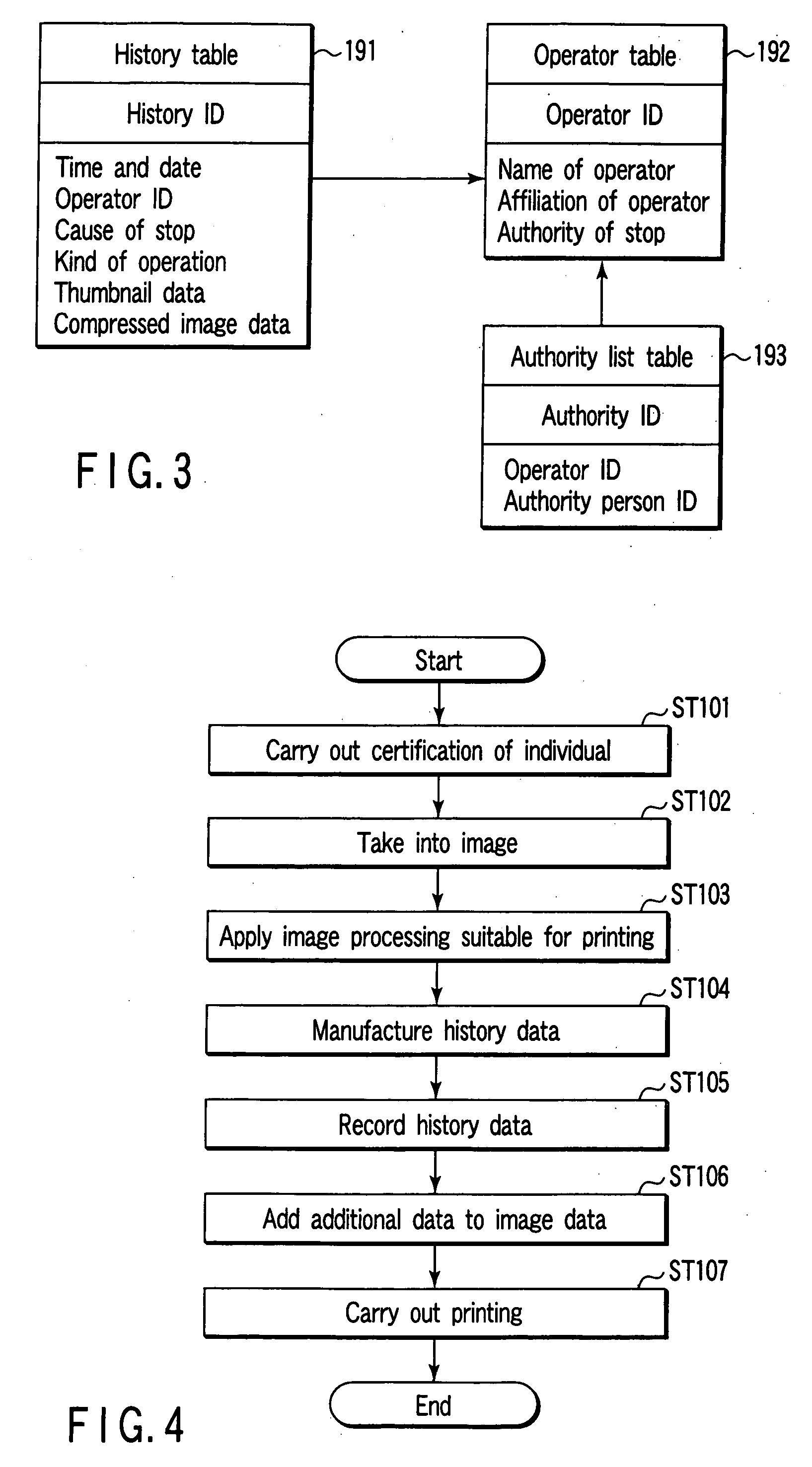
[0056] As shown in FIG. 6, in the MFP 1 according to the second embodiment, the history recording unit 19 is provided with an area to store a character list table (a character list data storage unit) 194. This character list table 194 stores a set of character rows that are printed in a security document or the like of which copying, printing, network scanning and the like are prohibited, for example, “secret” and “a customer list” and the character list ID.
[0057] Further, as shown in FIG. 8, the history manufacturing unit 17 is further provided with a converting unit 175 for converting image data into data from which a character can be read, a character recognition unit 176 for recognizing the character from this converted data, and a collating unit 177 for ...
third embodiment
[0063] Next, a third embodiment of the present invention will be described below. The same numeral references are given to the same parts as the above-described first embodiment and its detailed explanation is herein omitted.
[0064] As shown in FIG. 13, in the MFP 1 according to the third embodiment, the history manufacturing unit 17 is further provided with a history retrieving unit 178. The history retrieving unit 178 retrieves whether or not image data that substantially complies with the image data to be processed is recorded in the history recording unit 19. Processing the image data when the operations of scanning and copying are carried out, the MFP 1 configured in this manner displays the name of the operator who processes the image data on the display unit 132 when the approximately same processing of the image data is carried out in the past.
[0065] With reference to FIG. 14, the case of making the MFP 1 to scan the document after the operator mounts the document on the do...
PUM
 Abstract
Description
Claims
Application Information
 - R&D
- Intellectual Property
- Life Sciences
- Materials
- Tech Scout
- Unparalleled Data Quality
- Higher Quality Content
- 60% Fewer Hallucinations
Browse by: Latest US Patents, China's latest patents, Technical Efficacy Thesaurus, Application Domain, Technology Topic, Popular Technical Reports.
© 2025 PatSnap. All rights reserved.Legal|Privacy policy|Modern Slavery Act Transparency Statement|Sitemap|About US| Contact US: help@patsnap.com