Dual lane connection to dual redundant avionics networks

a technology of avionics network and dual lane connection, applied in the field of avionics network, can solve the problem of equal cost for each port and wiring that is associated with each connection

Inactive Publication Date: 2006-03-23
HONEYWELL INT INC
View PDF14 Cites 64 Cited by
  • Summary
  • Abstract
  • Description
  • Claims
  • Application Information

AI Technical Summary

Benefits of technology

[0009] In a third exemplary embodiment, an RDC end system in an Ethernet network includes, but is not limited to, a first port configured to couple to a first network in the Ethernet network, a second port configured to couple to a second network in the Ethernet network, a first processing lane coupled to the first port, a second processing lane coupled to the second port, and a cross-lane bus coupled to the first processing unit and the second processing unit. The first processing lane has a first input configured to receive input signals, a first output configured to transmit output signals, and a first processing unit coupled to the first input and the first output. The first processing unit is configured to control data flow to the first output, to the first port, and from the first input. The second processing lane has a second input configured to receive input signals, a second output configured to transmit output signals, and a second processing unit coupling the second input with the second output. The second processing unit is configured to control data flow to the second output, to the second port, and from the second input. The cross-lane bus is configured to transfer data between the first processing lane and the second processing lane.

Problems solved by technology

This design generally creates a significant number of connections to the AFDX network that results in an equally significant cost for each port and wiring that is associated with each connection.

Method used


Image

  • Dual lane connection to dual redundant avionics networks
  • Dual lane connection to dual redundant avionics networks
  • Dual lane connection to dual redundant avionics networks

Examples


Embodiment Construction

[0014] The following detailed description of the invention is merely exemplary in nature and is not intended to limit the invention or the application and uses of the invention. Furthermore, there is no intention to be bound by any theory presented in the preceding background of the invention or the following detailed description of the invention.

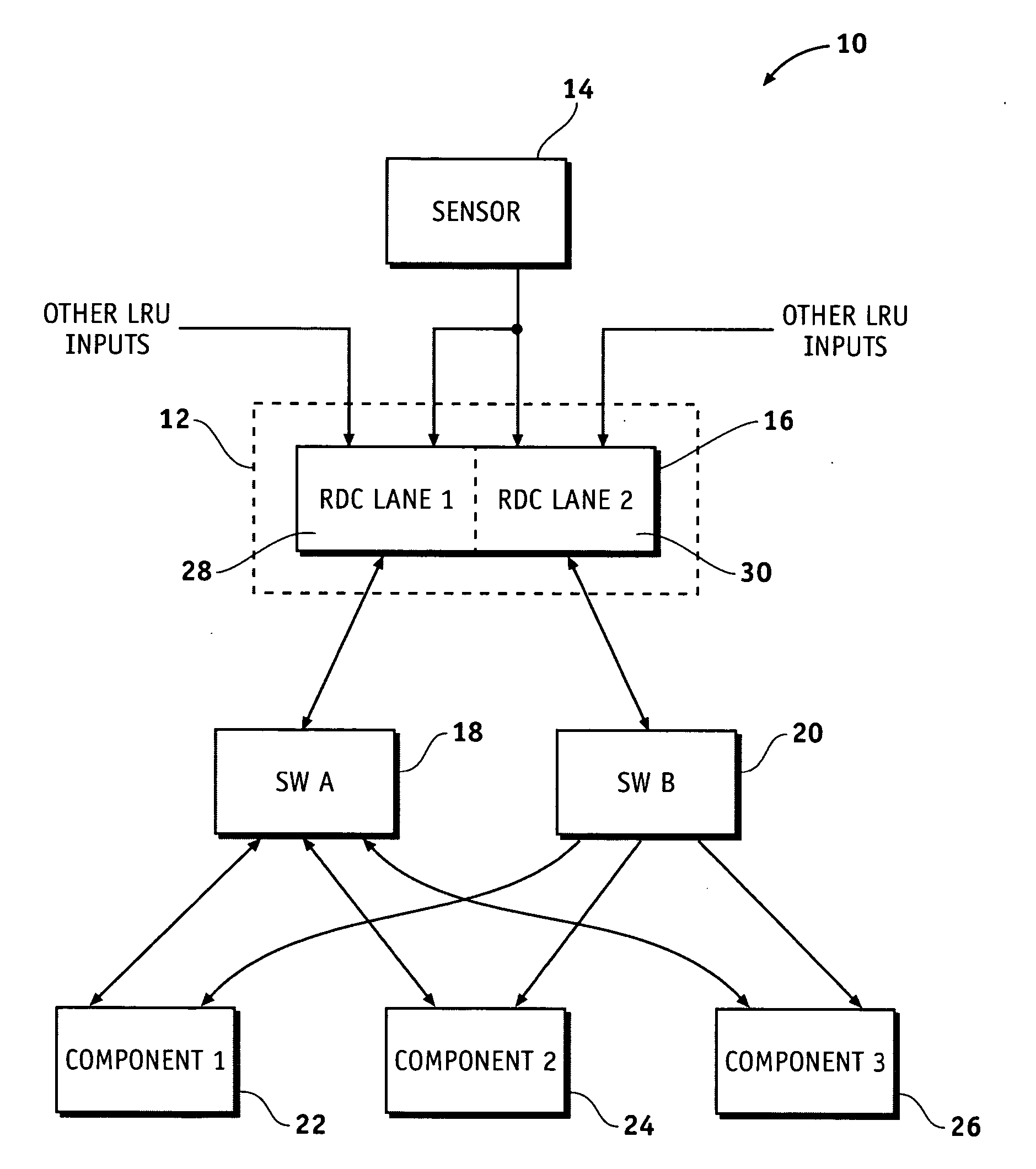
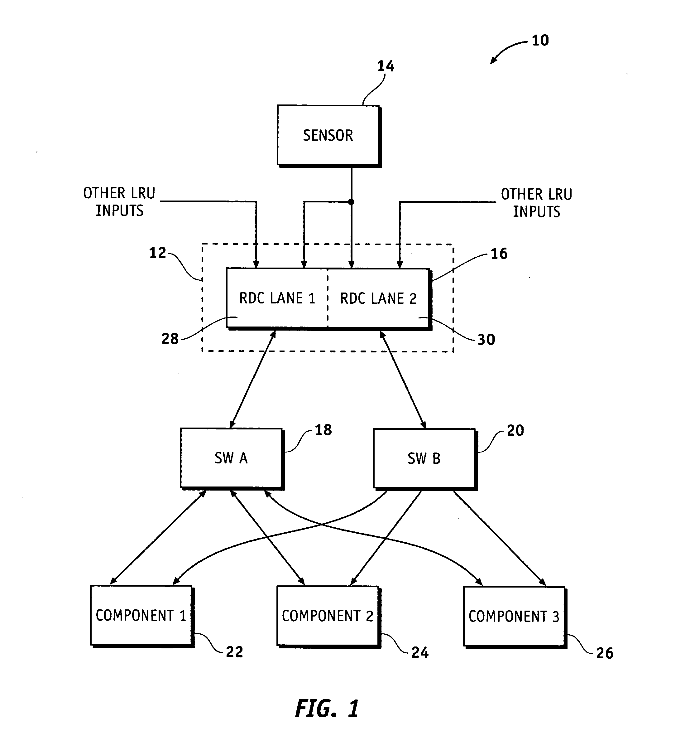
[0015] Referring to the drawings, FIG. 1 is a schematic diagram illustrating an exemplary embodiment of an avionics network 10 having a dual lane remote data concentrator (RDC) end system 12. The avionics network 10 is an Ethernet type network where one or more line replaceable units (LRUs), such as a sensor 14, are coupled to a dual lane RDC 16. The RDC end system 12 is coupled to a system data network (SDN) A and an SDN B via an “A” switch 18 and a “B” switch 20. Each of the switches 18, 20 is further coupled to various network components 22, 24, 26, such as processors, avionic instruments, and the like. Although not shown in FIG. 1, add...


PUM


Abstract

Apparatus and systems are provided for dual redundant avionics networks wherein a remote data concentrator (RDC) includes, but is not limited to, a line replaceable unit (LRU) input, a first processing lane coupled to the LRU input, a second processing lane coupled to the LRU input, and a processor coupled to the first processing lane and the second processing lane. The first processing lane has a first output. The second processing lane has a second output. The processor has a link coupling the first processing lane with the second processing lane and is configured to route data from at least one of the first output and the second output to an Ethernet. The link is configured to transfer data between the first processing lane and the second processing lane.

Description

FIELD OF THE INVENTION [0001] The present invention generally relates to avionics networks, and more particularly relates to redundant avionics networks. BACKGROUND OF THE INVENTION [0002] Ethernet type networks have been used in communication networks for implementing communication among various network components. An Ethernet network may be used to send or route data in a digital form by packets or frames. Each packet contains a set of data, and the packet is generally not interpreted while sent through the Ethernet network. The Ethernet network is typically composed of different equipment that subscribes to the network and connects to each other through switches. Each network subscriber can send packets in digital form generally at any time to one or more other subscribers. When a switch receives the packets, the destination equipment is determined, and the packets are switched to such equipment. In a switched full-duplex Ethernet type network, the term “full-duplex” refers to se...

Claims


Application Information

Patent Timeline
Patent Type & Authority Applications(United States)
IPC IPC(8): H04L1/00H04J3/14H04J1/16H04L12/26
CPCG05D1/0077G06F11/2007G06F11/2005
Inventor BIBBY, DAVEWILT, NICHOLAS
Owner HONEYWELL INT INC
Why Eureka
Try Eureka