Method and system for sub-aperture processing

a subaperture and processing method technology, applied in the field of ultrasonic imaging, can solve the problems of delay errors, delay errors may be within acceptable limits, and the large number of transducer elements substantially exceeds the number of beamforming channels typically available,

Active Publication Date: 2008-06-19
GENERAL ELECTRIC CO
View PDF8 Cites 26 Cited by
  • Summary
  • Abstract
  • Description
  • Claims
  • Application Information

AI Technical Summary

Benefits of technology

[0008]In accordance with further aspects of the present technique, a method of imaging is presented. The method includes receiving by a first plurality of transducer elements, one or more signals representative of imaging data. Also, the method includes process...

Problems solved by technology

Unfortunately, such a large number of transducer elements substantially exceeds the number of beamforming channels typically available even in most advanced ultrasound imaging systems.
However, while the delays for the connected transducer elements may be similar, the delays may not be identical, thereby resulting in delay errors.
In certain situations these delay errors may be within acceptable limits.
However, as the number of transducer elements connected to a beamforming channel increases, the delay errors may become unacceptable.
However, use ...

Method used


Image

  • Method and system for sub-aperture processing
  • Method and system for sub-aperture processing
  • Method and system for sub-aperture processing

Examples


Embodiment Construction

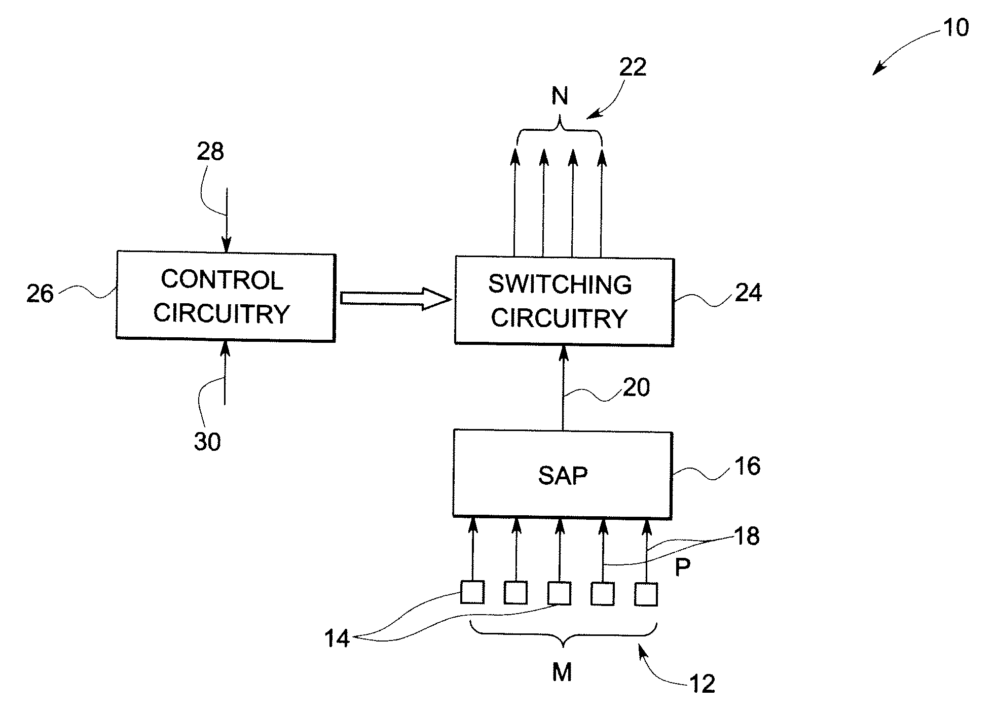
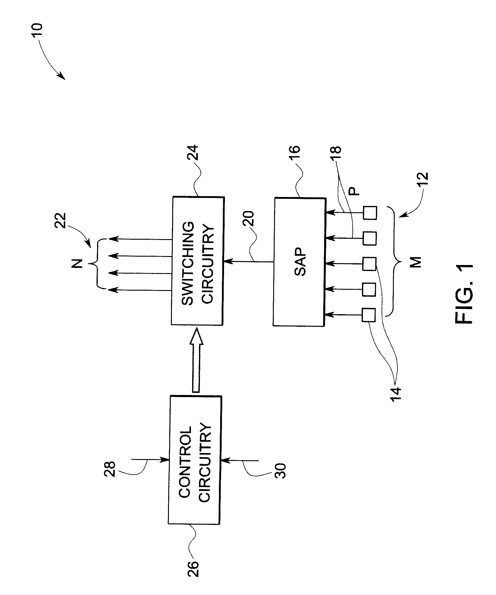
[0028]FIG. 1 illustrates an exemplary embodiment of a transducer assembly 10. In accordance with aspects of the present technique, the transducer assembly 10 may include a transducer array 12, where the transducer array 12 may include two or more (e.g., represented as ‘M’) transducer elements 14. In certain embodiments, the transducer elements 14 may include capacitive micromachined transducer elements, lead zirconate titanate (PZT) transducer elements, polyvinylidene difluoride (PVDF) transducer elements, or other transducer elements either known in the art or to be identified, as well as combinations thereof.

[0029]Further, the transducer assembly 10 may include one or more sub-aperture processors (SAPs) 16. In the illustrated embodiment of FIG. 1, a single SAP 16 is shown. However, certain transducer assemblies may include two or more (e.g., represented as ‘K’) SAPs. As will be appreciated, sub-aperture processors (SAPs) may be employed in transducer arrays having a relatively lar...


PUM


Abstract

A transducer assembly is provided including a transducer array comprising a plurality ‘M’ of transducer elements and a sub-aperture processor comprising a plurality ‘P’ of input channels and an output channel. The plurality ‘P’ of input channels is coupled to the ‘M’ transducer elements and a plurality ‘R’ of switching elements in operative association with the output channel of the sub-aperture processor to switchably couple the output channel to at least one of a plurality of ‘N’ system channels.

Description

BACKGROUND[0001]Embodiments of the application relate generally to ultrasound imaging, and more specifically to an arrangement of a plurality of sub-arrays on a transducer array.[0002]Conventional ultrasound imaging systems generally employ an array of transducer elements to transmit an ultrasound beam and subsequently receive a reflected beam from an object under interrogation. As will be appreciated, the array of transducer elements may include an arrangement in which the transducer elements are arranged in a two-dimensional array. Moreover, some ultrasound imaging systems may utilize large two-dimensional arrays of transducer elements often containing between 1000 and 20,000 transducer elements. Unfortunately, such a large number of transducer elements substantially exceeds the number of beamforming channels typically available even in most advanced ultrasound imaging systems.[0003]Previously conceived methods for performing beamforming on such large arrays of transducer elements...

Claims


Application Information

Patent Timeline
IPC IPC(8): A61B8/14G01S15/00A61B8/12
CPCG01S15/8925G10K11/341G01S15/8927A61B8/4494
Inventor HAZARD, CHRISTOPHER ROBERTHAIDER, BRUNO HANSWILDES, DOUGLAS GLENNBRUESTLE, REINHOLDSCHOISSWOHL, ARMINKRISTOFFERSEN, KJELL
Owner GENERAL ELECTRIC CO
Why Eureka
Try Eureka