Eye diagram determination during system operation

a technology of eye diagram and system operation, applied in the direction of transmission monitoring, line-transmission, line-transmission details, etc., can solve the problems of affecting time and voltage margins, affecting the results of eye scans, and presenting stresses in the system operating environment, so as to achieve sufficient operating electrical performance margins

Active Publication Date: 2010-10-26
ORACLE INT CORP
View PDF11 Cites 27 Cited by
  • Summary
  • Abstract
  • Description
  • Claims
  • Application Information

AI Technical Summary

Benefits of technology

[0009]In another embodiment, the service processor is configured to analyze the eye scan to determine various characteristics, such as sample time, a high voltage threshold, and a low voltage threshold and convey the resulting sample time, high voltage threshold, and low voltage threshold to the receiver. The receiver is configured to sample the

Problems solved by technology

These voltage and timing variations are caused, in part, by noise radiated from nearby electrical signals and by electrical noise on power and ground connections.
Once components are assembled into a system, the system operating environment presents stresses that may significantly alter the results of an eye scan.
For instance, variability in the system assembly, electrical noise from nearby circuitry, and electrical noise from power and ground connections may affect the time and voltage margins seen in a

Method used


Image

  • Eye diagram determination during system operation
  • Eye diagram determination during system operation
  • Eye diagram determination during system operation

Examples


Embodiment Construction

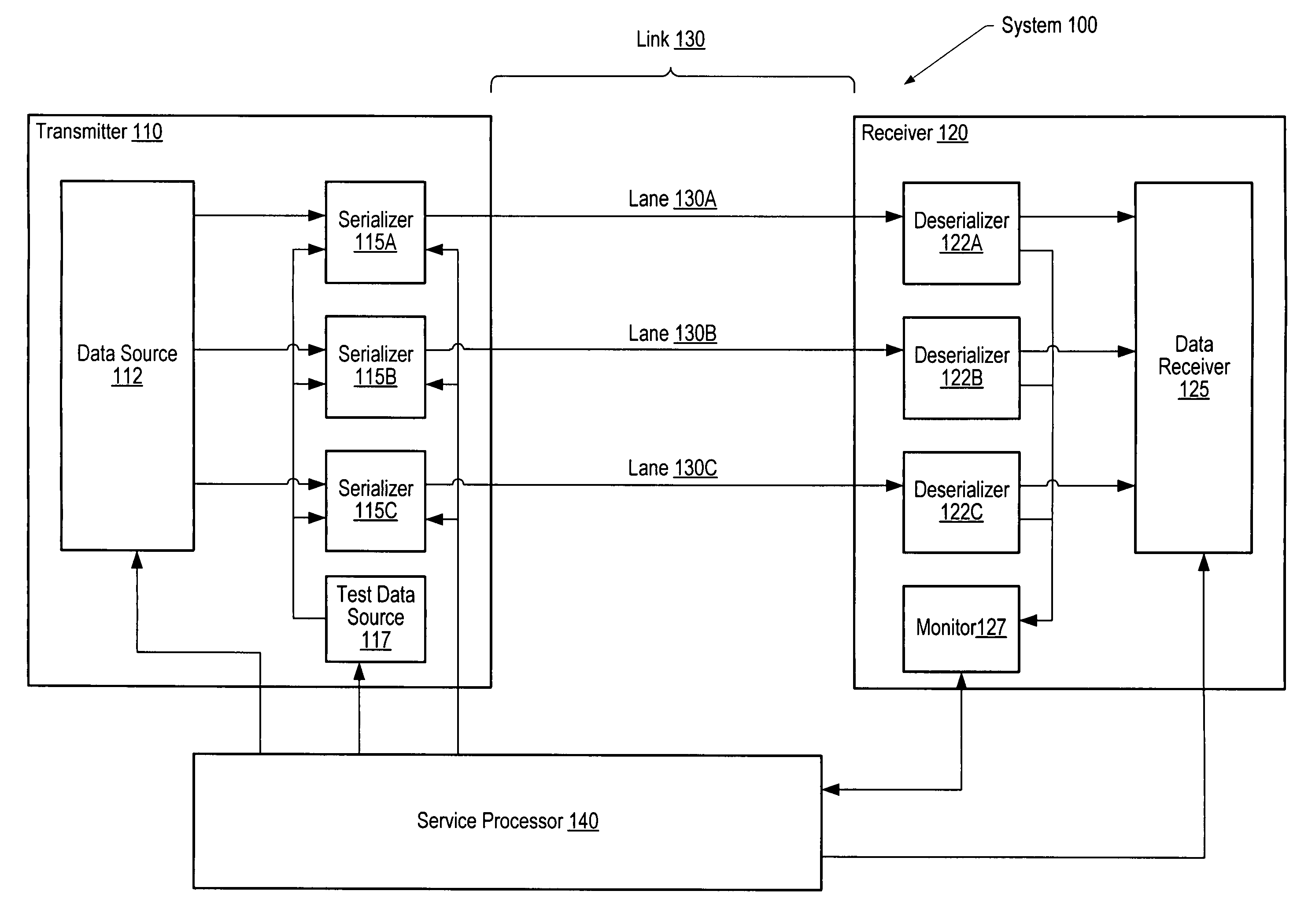
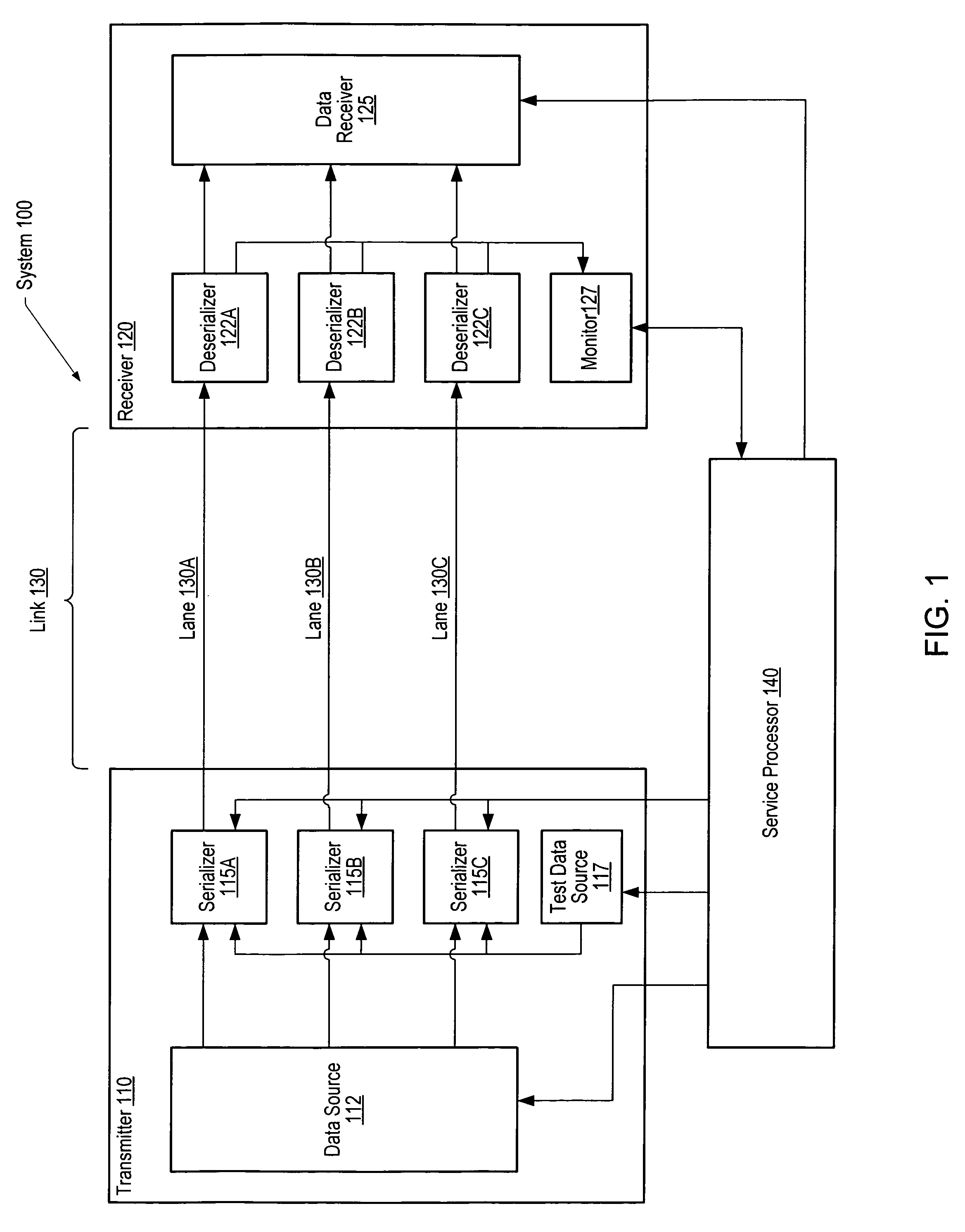
[0017]FIG. 1 is a generalized block diagram of a system 100 that may perform eye scan testing of a serial communications link. In one embodiment, system 100 includes a transmitter 110 coupled to a receiver 120 through link 130. A service processor 140 is provided to control the operation of communications between transmitter 110 and receiver 120. In the illustrated embodiment, link 130 includes lanes 130A-130C. It will be appreciated that link 130, in various embodiments, may include fewer than three or more than three lanes depending on design considerations such as space constraints, the number of bits in the parallel communications link, system cost, etc.

[0018]In one embodiment, transmitter 110 includes a data source 112 coupled to a set of serializers 115A-115C. Transmitter 110 may also include a test data source 117 that is coupled to each of serializers 115A-115C. Each of serializers 115A-115C may be configured by service processor 140 to accept input from either data source 1...


PUM


Abstract

A system for testing a communications link. A system includes a transmitter, a receiver, a digital communications link, and a service processor. The digital communications link includes a plurality of lanes through which the transmitter is coupled to the receiver. During an operating mode of the digital communications link and during otherwise normal system operation, the service processor (a) switches a selected one of the plurality of lanes from the operating mode to a test mode, (b) performs an eye scan of the selected lane, (c) stores data corresponding to the eye scan of the selected lane, and (d) returns the selected lane to the operating mode.

Description

BACKGROUND OF THE INVENTION[0001]1. Field of the Invention[0002]This invention relates to communications links between integrated circuits and, more particularly, to testing of communications links between integrated circuits during system operation.[0003]2. Description of the Related Art[0004]Increasing bandwidth demands on communications links between integrated circuits have led to designs that replace wide parallel links with very high-speed serial links, thereby potentially simplifying circuit board layout and reducing timing skew problems while achieving higher net bandwidth. Multi-gigabit-per-second serial links have become a common means for communicating data between integrated circuits on a single board or across a backplane between boards. In a typical serial communications link, a Serializer / Deserializer (SerDes) is used to convert a set of parallel signals to a serial bit stream and vice versa. Often, a multiple-byte set of signals is divided into 8-bit segments, each s...

Claims


Application Information

Patent Timeline
IPC IPC(8): H04B3/46
CPCH04B3/32H04B3/466
Inventor DOBLAR, DREW G.
Owner ORACLE INT CORP
Why Eureka
Try Eureka