Image registration device

a technology of image registration and axis rotation, applied in optics, electromagnetography, instruments, etc., can solve the problems of visual print quality degradation, registering errors along the axis of rotation of the respective image, and registering errors in the process direction, etc., to achieve the effect of improving the axial image registration

Active Publication Date: 2006-03-23
OCE TECH
View PDF3 Cites 60 Cited by
  • Summary
  • Abstract
  • Description
  • Claims
  • Application Information

AI Technical Summary

Benefits of technology

[0003] Thus it is an object of the present invention to provide an image registration device which allows for improved axial image registration in all circumstances.
[0004] It is a further object of the present invention to provide an image registration device which adjusts for any axial image misregistration, in situ and quasi instantaneously, without affecting the productivity of the image production system.
[0010] The feature that, in operation, the rotating image carrying element is enforced to axially follow the rotating image receiving element or vice versa by a mechanical construction using flanges on the respective rotating elements and a further rotating element in rolling contact with the flanges is advantageous as it allows to adjust for any axial mispositioning, quasi instantaneously and continuously. As this takes place in the operative state, i.e., the recording medium is fed in sheet or in web form through the transfer zone and hence prints or copies of images are generated, this registration process does not negatively affect the productivity of the printer or copier. When pressing the further rotating element towards the flanges with a predetermined pressure, the configuration is such that either the image carrying element or the image receiving element remains in position. In other words, the rotatable element which maintains its axial position despite the predetermined pressure exerted by the pressure exerting means, is axially confined. For instance, in order to axially confine one of the rotatable elements, one may opt to rigidly connect that rotatable element to the base support frame of the image production system.

Problems solved by technology

The slightest misregistration may lead to visual print quality degradation.
Rotational position errors lead to registering errors in the process direction, i.e., the propagation direction of the medium.
Lateral position errors lead to registering errors along the axis of rotation of the respective image-carrying and / or image-receiving members, i.e., the direction perpendicular to the process direction.
For instance, lateral position errors may be caused by wobbling of a rotating image-carrying and / or image-receiving member, thermal effects resulting in variations of the dimensions or the position of the image-carrying and / or image-receiving member.
Although the described approach for limiting axial image misregistration may work fine in most operating conditions, it does not deal effectively with sudden changes in the lateral position of one or more of the cycling members, such as e.g., changes caused by leaning on or accidentally pushing against the printing system.

Method used


Image

  • Image registration device
  • Image registration device
  • Image registration device

Examples


Embodiment Construction

[0021] The present invention is described in detail and in sequel in the appended drawings. Several embodiments are disclosed. It is apparent however that a person skilled in the art can imagine other equivalent embodiments or other ways of executing the present invention.

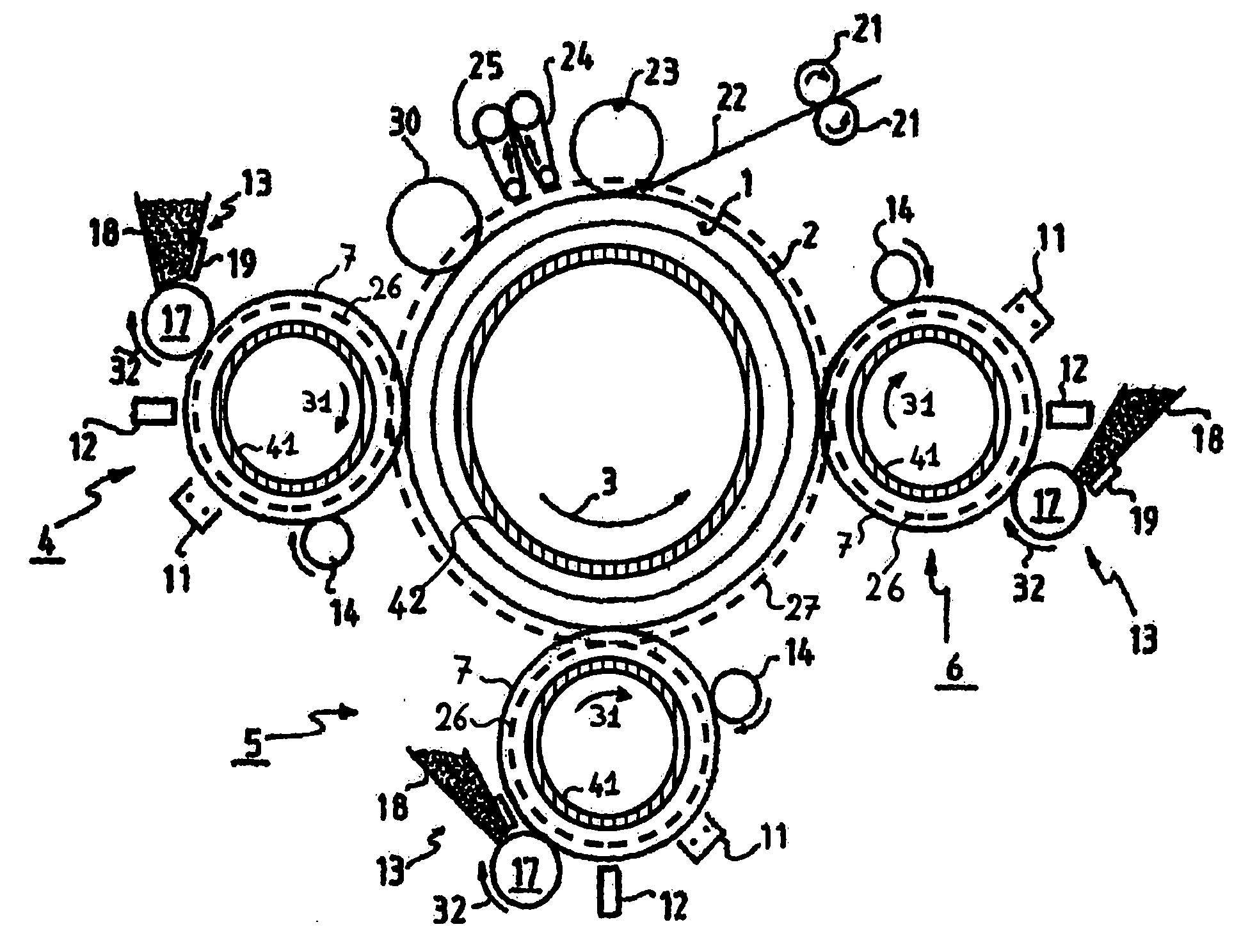
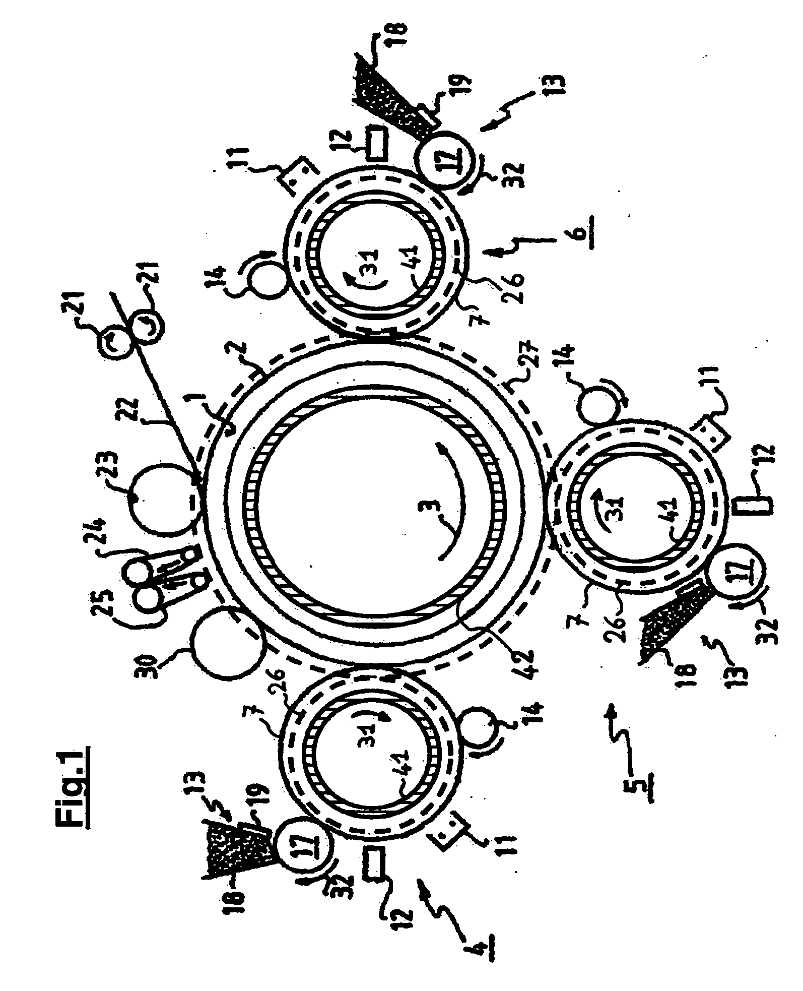
[0022] A printing system capable of printing on sheets of a recording medium is depicted in FIG. 1. The printing system comprises an image transfer member, which can be moved cyclically. The image transfer member is an endless member, such as e.g., a drum or a belt. In this case the image transfer member is a cylindrical drum, which can be moved in the direction of the arrow. The image transfer member is constructed of a metal sleeve, e.g., aluminium, with an elastomeric covering. Optionally, the image transfer member may be provided with an outer layer of silicone rubber, or a PTFE, or a fluororubber, e.g., by means of a coating. One or more process colors are available on the printing system, dependent on whethe...


PUM


Abstract

An image registration device for an image production system is disclosed which adjusts any axial image misregistration in situ and quasi instantaneously. This image registration device contains, in operation, a rotating image carrying element and a rotating image receiving element in rolling contact with each other and each having a flange co-axially mounted on their respective shafts. The image registration device includes a further rotating element in rolling contact with the flanges of the rotating elements to ensure that the image carrying element axially follows the image receiving element or vice versa to establish axial image registration.

Description

FIELD OF THE INVENTION [0001] The present invention is directed to an image registration device for an image production system for transferring separation images of a marking substance, including ink and toner, in register from a rotatable image-carrying member to a rotatable image-receiving member. BACKGROUND OF THE INVENTION [0002] Image production systems, such as printers and copiers, often include a rotatable image-receiving member, usually in the form of a belt or a drum, for receiving on its surface a marking substance, such as toner or ink, in image form, from a rotatable image carrying member, usually also in the form of a drum or a belt. The image-receiving member may either receive the image directly on its surface or on a recording medium conveyed on its surface. The images of marking substance are transferred from the image-carrying member to the image-receiving member in a transfer zone where the image-receiving member and the image-carrying member are in rolling conta...

Claims


Application Information

Patent Timeline
Patent Type & Authority Applications(United States)
IPC IPC(8): G06K9/32
CPCG03G15/0131G03G2215/0154G03G15/757
Inventor SMEIJERS, JOHANNES H. L.
Owner OCE TECH
Why Eureka
Try Eureka