

Systems and methods for implementing unique offsetting stacker registration using omni-directional wheels for set compiling in image forming devices
a technology of image forming device and unique stacker, which is applied in the direction of electrographic process, instruments, transportation and packaging, etc., can solve the problem that the processing of documents responsive to directed print jobs can be particularly complex
- Summary
- Abstract
- Description
- Claims
- Application Information
AI Technical Summary
Benefits of technology
Problems solved by technology
Method used
Image

Examples
Embodiment Construction
[0007]Operating and processing speeds for completing intricate print jobs in complex image forming systems continue to increase. The demands for precision in registration and alignment of sets of documents remain very high. This combination of factors places ever increasing stress on rapidly linearly reciprocating components in conventional systems, such as, for example, side tampers, causing mechanical components to fail. To address these issues, image forming device manufacturers have begun exploring a range of alternative solutions.
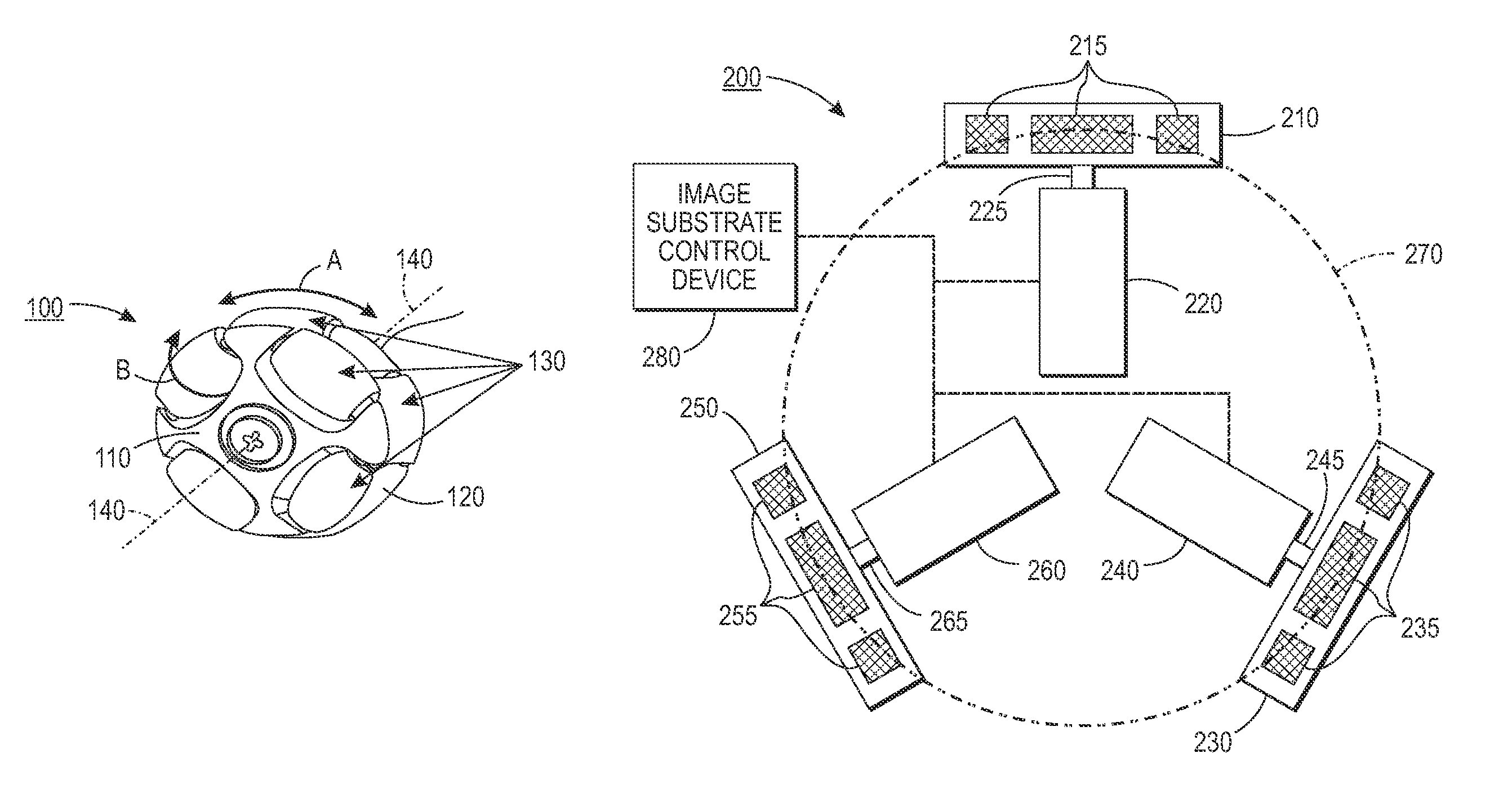
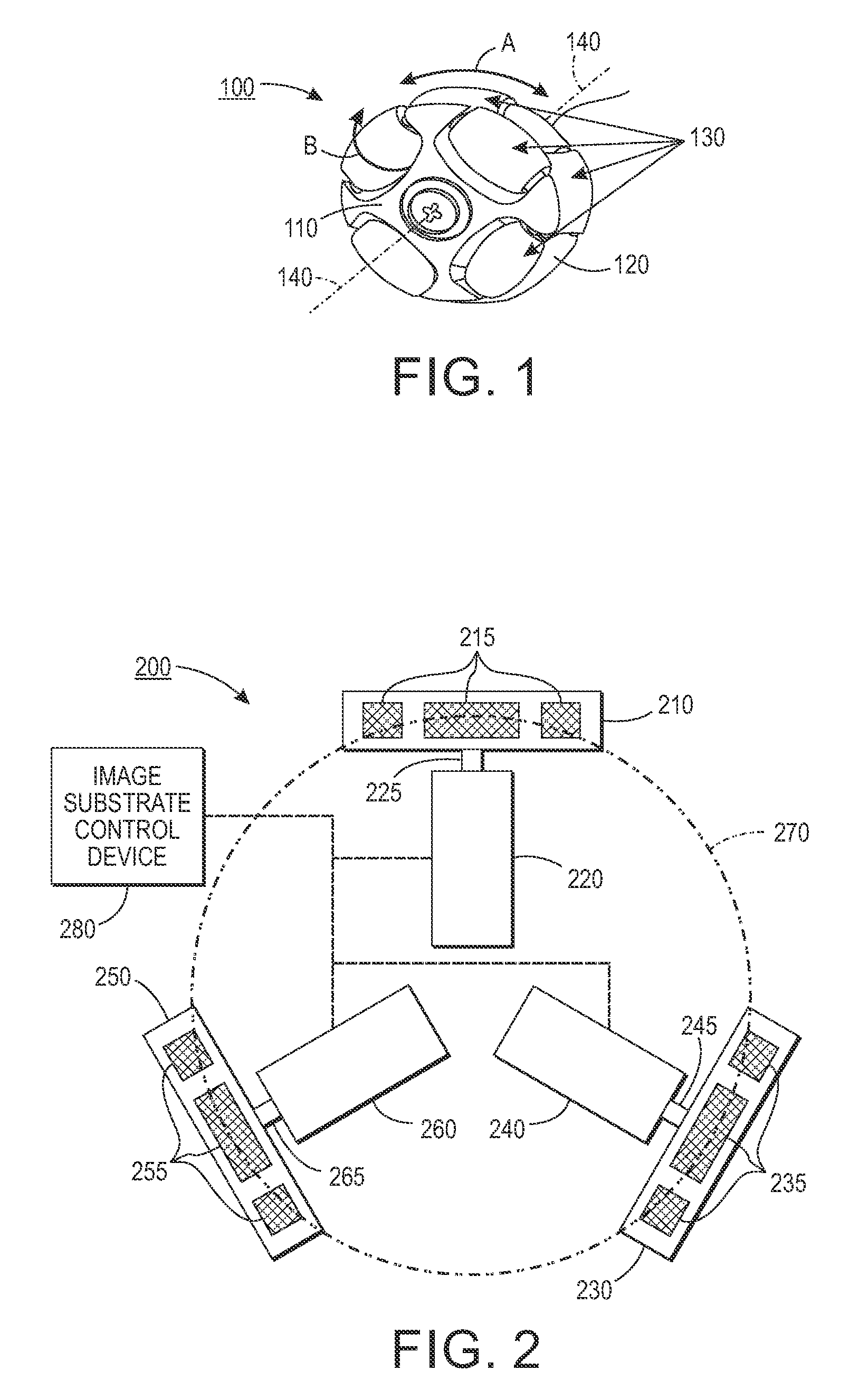
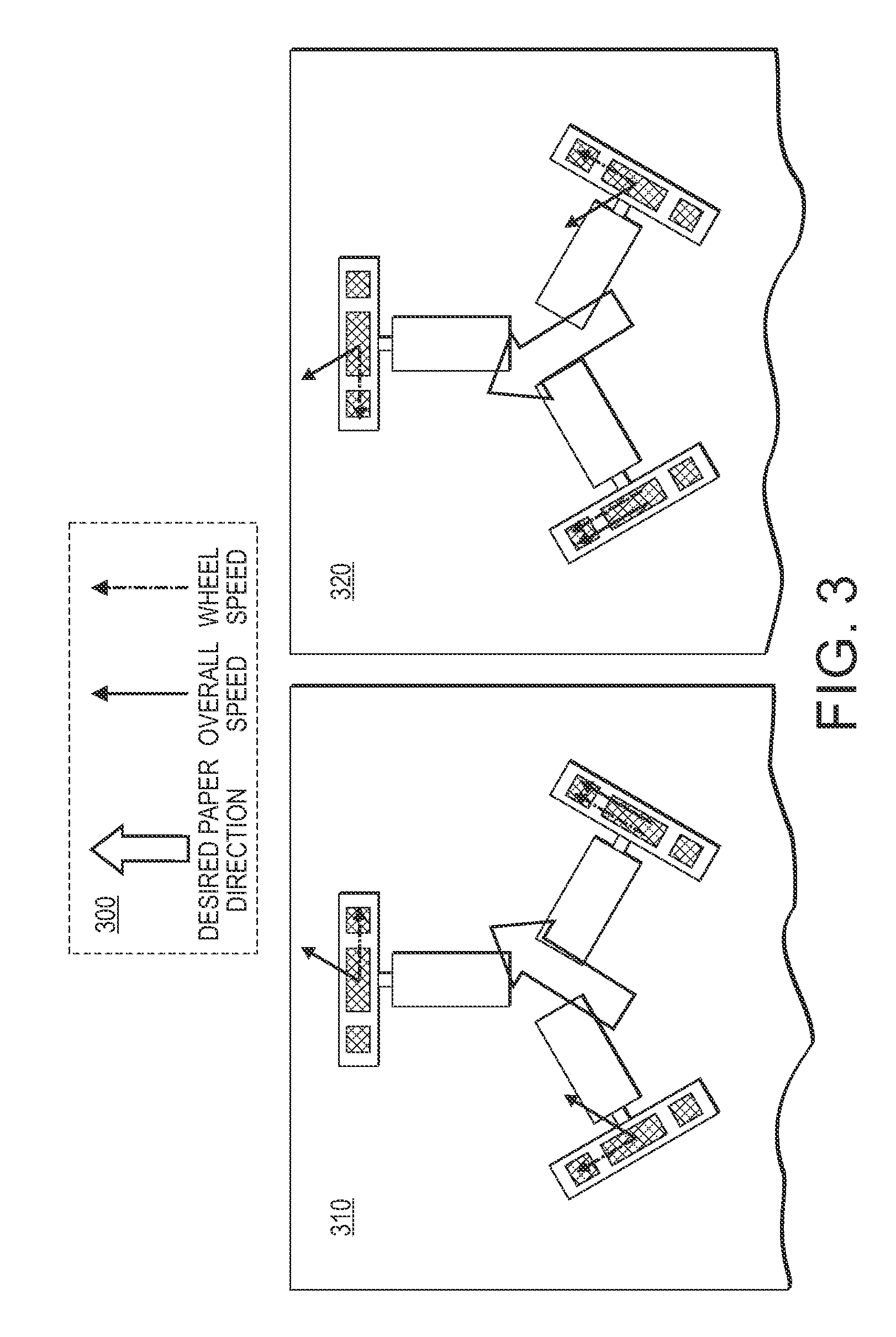
[0008]In a currently-implemented solution as a sheet of image receiving media substrate is ejected from a processing unit, a scuffer component may drive the sheet to a registration wall to establish registration in a process direction. The scuffer is then lifted so that mechanical paddle tampers can effect registration of the sheet in a cross-process direction. This process is repeated until an entire set is compiled and ready for stapling. In typical ...
PUM
| Property | Measurement | Unit |
|---|---|---|
| speeds | aaaaa | aaaaa |
| traction force | aaaaa | aaaaa |
| size | aaaaa | aaaaa |
Abstract
Description
Claims
Application Information