Apparatus, program, and method for image tone transformation, and electronic camera

a technology of image tone and program, applied in the field of apparatus, program and method for image tone transformation, can solve the problems of excessive exaggeration of shadows, difficult to perform delicate processing, and prior art cannot realize image processing, and achieve the effect of well-balanced adjustment of brightness/darkness balance and tone ris

Active Publication Date: 2006-03-23
NIKON CORP
View PDF11 Cites 52 Cited by
  • Summary
  • Abstract
  • Description
  • Claims
  • Application Information

AI Technical Summary

Benefits of technology

[0016] Therefore, it is an object of the present invention to provide a tone transformation technique enabling well-balanced adjustment of the brightness / darkness balance and of the rise of the tone in a detailed portion.

Problems solved by technology

However, this prior art cannot realize image processing such as particularly emphasizing the tone of a detailed portion so as to attain an image with a higher contrast and a more detailed expression.
With the Retinex method, it has been difficult to perform delicate processing such as adjusting the rise of the tone of a detailed portion while adjusting the general brightness / darkness balance of the whole image.
However, the processing as expressed by the equation [100] has sometimes resulted in excessively exaggerating shadows.
There has been a problem that, when an image including a person is subjected to the strong gamma correction, the exaggeration of shadows increases, which causes unnatural finish of the image of the person and a conspicuous unnatural impression, compared with a case where linear image processing is applied to brightness of a subject.
The processing with the Epsilon filter has another problem that it is complicated and takes a lot of time.
On the other hand, the use of a simple low pass filter instead of the Epsilon filter has a problem of causing a halo in a portion having a great luminance difference.
In this case it is difficult to obtain a favorable result for respective color components of an image such as a color image having a plurality of components even if the processing as expressed by the following equations is applied thereto.

Method used


Image

  • Apparatus, program, and method for image tone transformation, and electronic camera
  • Apparatus, program, and method for image tone transformation, and electronic camera
  • Apparatus, program, and method for image tone transformation, and electronic camera

Examples


first embodiment

>

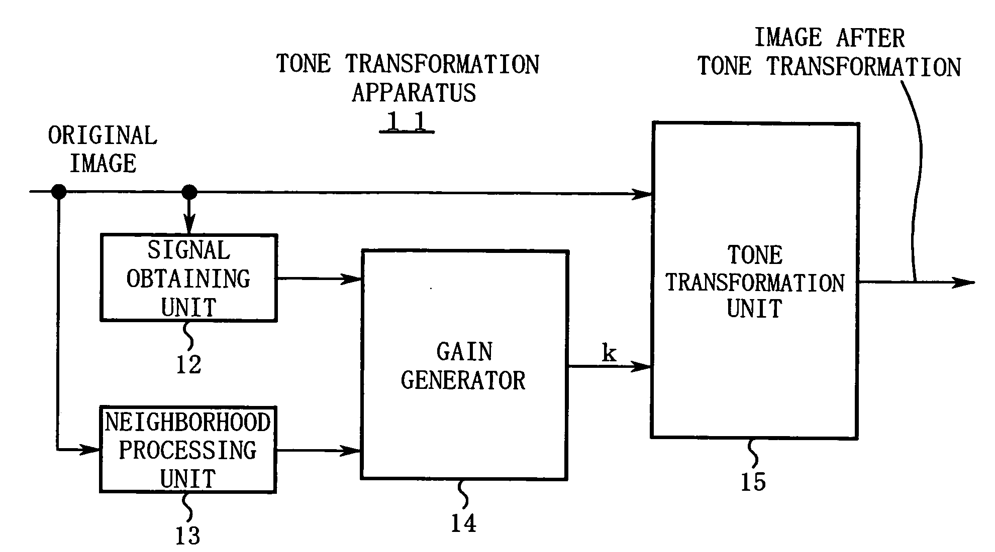
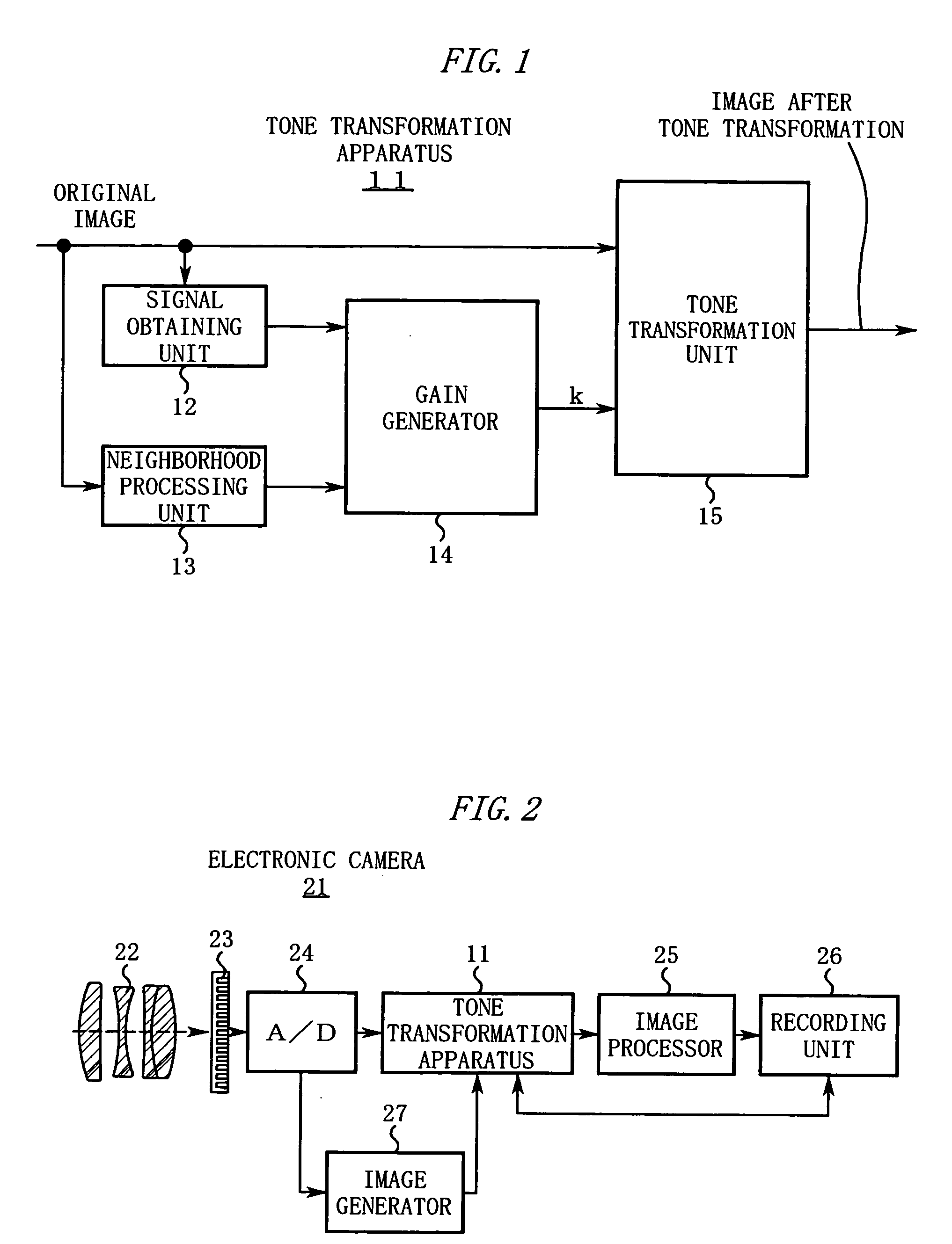
[0059]FIG. 1 is a diagram showing a configuration of a tone transformation apparatus 11.

[0060] In FIG. 1, the tone transformation apparatus 11 includes the following constituent features: [0061] (1) a signal obtaining unit 12 to obtain a signal Z indicating brightness or the like of each pixel of an original image. [0062] (2) a neighborhood processing unit 13 to extract a neighborhood area from each pixel of the original image and processes pixels in the neighborhood area to obtain a signal ZL. [0063] (3) a gain generator 14 to find a transformation gain k for each pixel according to the signal Z and the signal ZL. [0064] (4) a tone transformation unit 15 to transform the tone by multiplying a signal of each pixel of the original image by the transformation gain k for each pixel.

[0065] The above-described tone transformation apparatus 11 may be partly or entirely composed of hardware. Alternatively, the tone transformation apparatus 11 may be realized on a computer as software by...

case 1

(case 1) When R, G, and B are the plural color components composing the original image, R′, G′ B′ signals resulting from the transformation using the transformation gain are calculated by the following.

R′=k·R, G′=k·G, and B′=k·B

case 2

(case 2) In a case of a brightness signal indicating luminance or an amount of brightness and input signals indicating a plurality of color differences, the brightness signal is multiplied by the transformation gain k, whereby a brightness signal after the tone transformation is calculated. Further, color differences C1′, C2′ after the tone transformation are calculated by

C1′=k·C1 and C2′=k·C2,

where C1 and C2 are the input signals indicating the plural color differences.

[0122] Some tone transformation is accompanied by a change in visual saturation. For correcting this saturation change, a transformation gain k1 after correction is used instead of the transformation gain k.

C1′=k1·C1 and C2′=k1·C2

[0123] Here, the transformation gain k1 after the correction is found by

k1=k·t(Z) or k1(Z, ZL)=k(t(Z), ZL),

where t(Z) is a function monotonically changing with respect to Z. Note that the function t(Z) is preferably determined based on experiments so that the visual saturation become...


PUM


Abstract

A tone transformation apparatus of the present invention extracts or generates a signal Z[i, j] according to a pixel value of a pixel [i. j] of an original image or a pixel value of its immediate neighborhood. Further, it extracts or generates a signal ZL[i, j] according to a pixel value of a neighborhood area of the pixel [i, j]. A transformation gain k for the pixel [i. j] is determined according to these signals Z, ZL. For the tone transformation, a color component or the like of the pixel [i, j] is multiplied by the transformation gain k for the pixel [i. j].

Description

CROSS REFERENCE TO RELATED APPLICATION [0001] This application is based upon and claims the benefit of priority from Japanese Patent Application Nos. 2004-272562 and 2004-272596, both filed on Sep. 17, 2004, and Nos. 2005-095625 and 2005-095630, both filed on Mar. 29, 2005, the entire contents of which are incorporated herein by reference. BACKGROUND OF THE INVENTION [0002] 1. Field of the Invention [0003] The present invention relates to an apparatus a program, and a method for image tone transformation, and an electronic camera. [0004] 2. Description of the Related Art (Prior Art 1) [0005] Japanese Unexamined Patent Application Publication No. Hei 4-150171 (hereinafter, referred to as Patent document 1) describes a conventional tone transformation technique. [0006] According to this prior art, a luminance signal Y is calculated by the following equation: Y=0.3·*R+0.59·G+0.11−B  [1][0007] Next, predetermined tone transformation Y′=f(Y) is applied to the luminance signal Y to find ...

Claims


Application Information

Patent Timeline
Patent Type & Authority Applications(United States)
IPC IPC(8): G03B7/00
CPCG06T5/008H04N9/77H04N1/6027G06T2207/10024
Inventor UTAGAWA, KEN
Owner NIKON CORP
Why Eureka
Try Eureka