Platemaking method and platemaking apparatus

a platemaking method and platemaking technology, applied in the field of platemaking methods and platemaking apparatuses, can solve the problems of consuming a relatively long time in the platemaking process, and achieve the effect of reducing the platemaking tim

Inactive Publication Date: 2006-03-30
DAINIPPON SCREEN MTG CO LTD
View PDF14 Cites 29 Cited by
  • Summary
  • Abstract
  • Description
  • Claims
  • Application Information

AI Technical Summary

Benefits of technology

[0007] The object of this invention, therefore, is to provide a platemaking method and a platemaking apparatus that realizes a shortened platemaking time through efficient use of a laser beam.

Problems solved by technology

Thus, there is a drawback of consuming a relatively long time in the platemaking process.

Method used


Image

  • Platemaking method and platemaking apparatus
  • Platemaking method and platemaking apparatus
  • Platemaking method and platemaking apparatus

Examples


Embodiment Construction

[0040] Embodiments of this invention will be described hereafter with reference to the drawings.

[0041] The following description will be devoted first to the first characteristic of this invention that shortens a platemaking time by performing an engraving operation in two processes. One of these processes is a precision engraving process for engraving a flexo printing plate 10 to a maximum depth dp by irradiating it at a precision engraving pixel pitch pp with a precision engraving beam L1. The other process is a coarse engraving process for engraving the flexo printing plate 10 to a relief depth d by irradiating it at a coarse engraving pixel pitch pc with a coarse engraving beam L2. Subsequently, the description will deal with the second characteristic of the invention that shortens a platemaking time, while maintaining high platemaking accuracy, by using a laser beam efficiently.

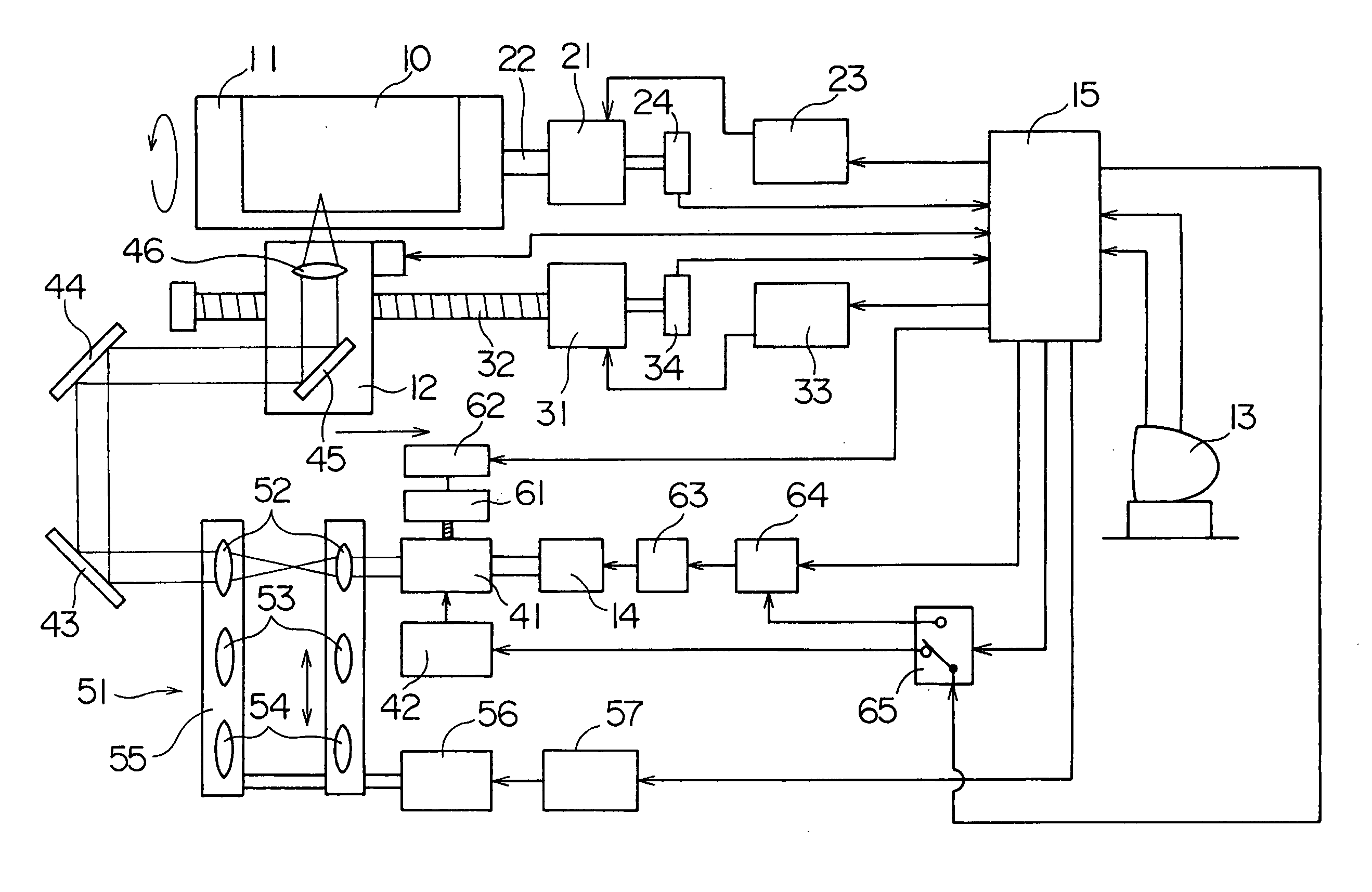
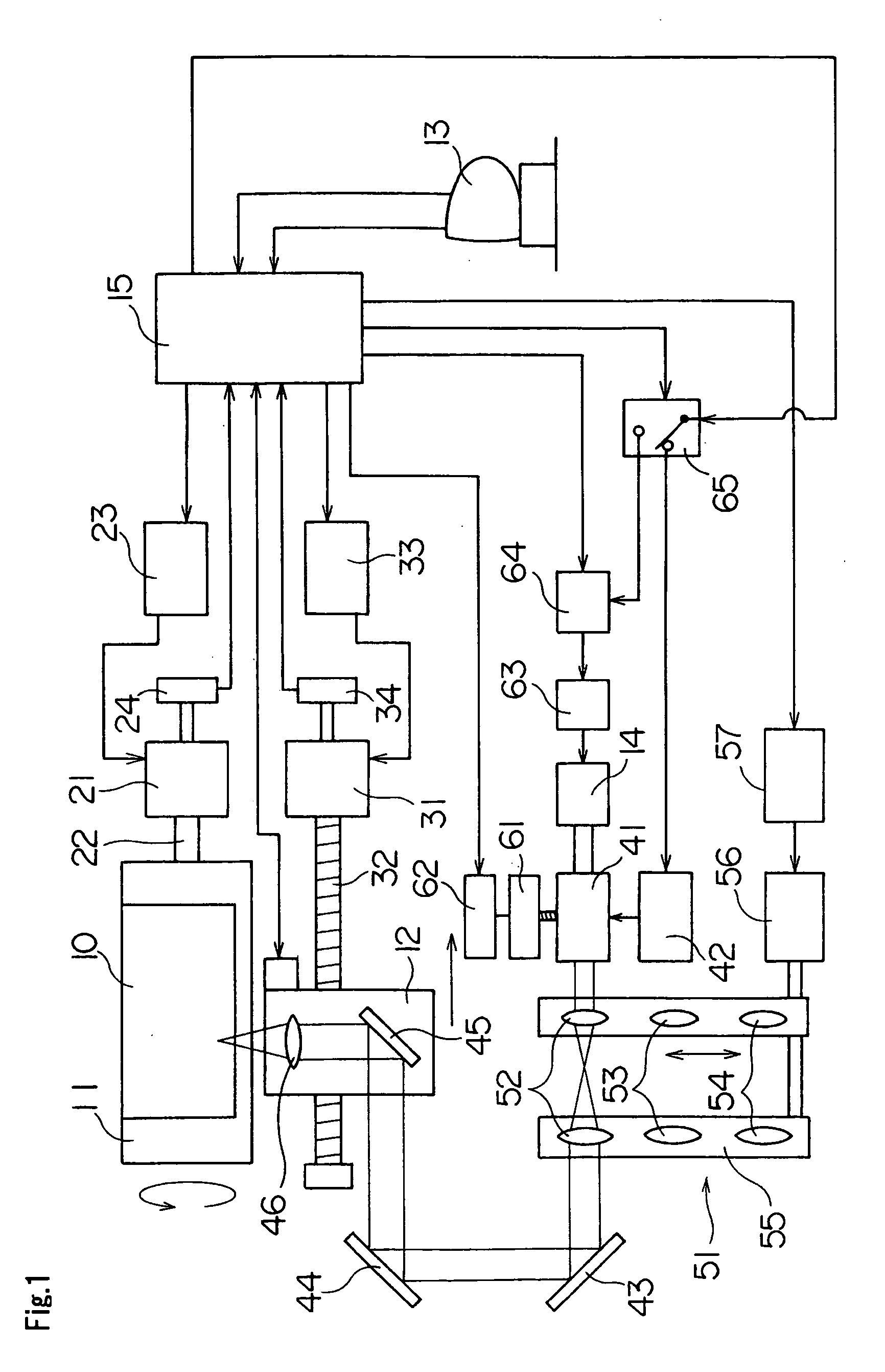
[0042]FIG. 1 is a block diagram showing an outline of a laser engraving machine which is a platemak...


PUM

PropertyMeasurementUnit
diameteraaaaaaaaaa
diameteraaaaaaaaaa
poweraaaaaaaaaa

Abstract

A flexo direct printing plate is engraved in two processes. One is a precision engraving process for irradiating the flexo direct printing plate at a precision engraving pixel pitch with a precision engraving beam having a small diameter, to engrave the plate to a maximum depth. The other is a coarse engraving process for irradiating the flexo direct printing plate at a coarse engraving pixel pitch larger than the precision engraving pixel pitch, with a coarse engraving beam having a large diameter, to engrave the plate to a relief depth.

Description

BACKGROUND OF THE INVENTION [0001] 1. Field of the Invention [0002] This invention relates to a platemaking method and a platemaking apparatus for imaging on image recording materials such as printing plates or printing cylinders (both referred to as printing plates thereafter) for use in relief printing such as flexography, letterpress and in intaglio printing such as photogravure. [0003] 2. Description of the Related Art [0004] Conventional platemaking apparatus of the type noted above include a laser engraving machine as described in U.S. Pat. No. 5,327,167, for example. This laser engraving machine makes relief printing plates by scanning an image recording material with a laser beam emitted from a laser source to engrave the surface of the recording material. The machine includes a modulator for modulating the laser beam emitted from the laser source, a recording drum rotatable with the image recording material mounted peripherally thereof, and a recording head movable in a dir...

Claims


Application Information

Patent Timeline
Patent Type & Authority Applications(United States)
IPC IPC(8): B41N3/00
CPCB41C1/05B41C1/02
Inventor OGAWA, HIDEAKI
Owner DAINIPPON SCREEN MTG CO LTD
Why Eureka
Try Eureka