Torque converter for vehicle

Inactive Publication Date: 2006-03-30
KOREAN POWERTRAIN
12 Cites 6 Cited by

AI-Extracted Technical Summary

Problems solved by technology

When load applied to an engine is increased, the power transmission rate may be deteriorated.
However, when the thickness of the blades is increased, a volume of the actuating chamber is reduced by as much as the volume occupied by the increased thickness, thereby deteriorating the converting efficiency.
Furthermore, when the blades increased in the thickness are ...

Method used

[0049] Each extending section 48 of each projection is bent to closely contact the surface of the shell (or core), thereby maintaining the fixed state. That is, fixed state can be maintained by only bending the extending section 48. Particularly, in order to reduce the movement, the extending section is bent in an opposite direction to the adjacent extending section.
[0056] By the above-described structure, since the race 58 of the bearing is not rotated relative to the retainer 52 even when the turbine rotates, the wear of the retainer can be prevented.
[0058] A retainer 52 of this embodiment is provided with a hole 64 to supply oil used as lubricant to a one-way clutch 50 through the hole 64. In order to more effectively supply the oil to the hole 64, an oil supplying groove 66 is formed on the retainer.
[0060] In order to enhance the fluidity of the oil, the oil supplying groove 66 is formed in a circular arc shape. That is, a width ...

Benefits of technology

[0024] It is an objective of the present invention to provide a torque converter for a vehicle, which is des...

Abstract

A torque converter for a vehicle includes a front cover integrally formed with a boss to which a crank shaft of an engine side is connected, an impeller connected to the front cover to rotate together with the front cover, a turbine disposed facing the impeller, a stator disposed between the impeller and the turbine to convert flow of oil directed from the turbine, a lockup clutch mechanism for directly connecting the engine to the turbine. A blade of the impeller and/or the turbine is provided with inner and outer projections coupled to shell and core of the impeller and/or the turbine. Each of the inner and outer and inner projections includes a base located on a slit formed on the shell/core and an extending section extending from the base, the extending section being bent after penetrating the slit.

Application Domain

Technology Topic

Image

  • Torque converter for vehicle
  • Torque converter for vehicle
  • Torque converter for vehicle

Examples

  • Experimental program(1)

Example

[0037] Reference will now be made in detail to the preferred embodiments of the present invention, examples of which are illustrated in the accompanying drawings Wherever possible, the same reference numbers will be used throughout the drawings to refer to the same or like parts.
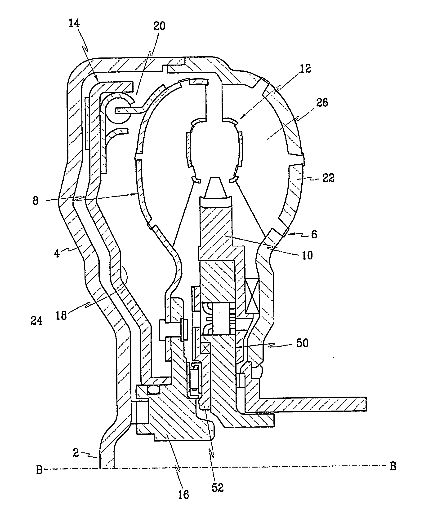
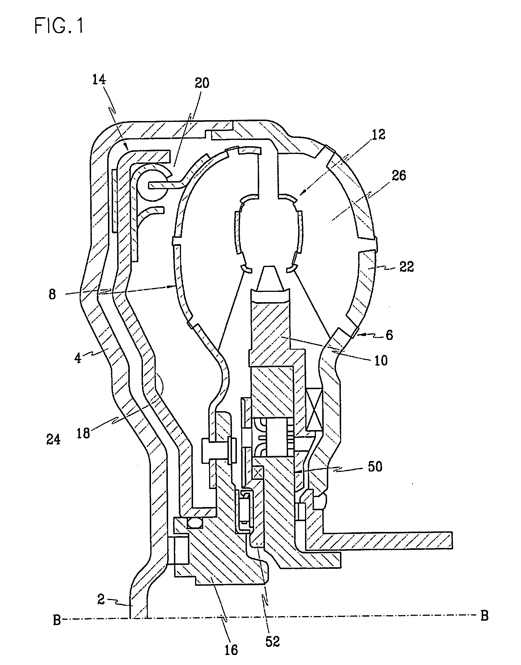
[0038]FIG. 1 is a half-sectional view of a torque converter according to an embodiment of the present invention, in which a left end of torque converter is connected to an engine and the torque converter has upper and lower halves that are identical to each other with reference to line B-B.
[0039] The inventive torque converter includes a front cover 4 integrally formed with a boss 2 to which a crank shaft of an engine side is connected, an impeller 6 connected to the front cover to rotate together, a turbine disposed facing the impeller 6, and a stator 10 disposed between the turbine 8 and the impeller 6 to cover the flow of oil directed from the turbine 8.
[0040] The impeller, turbine and stator 6, 8 and 10 define a torque fluid actuating portion 12 having a central axis identical to that of the front cover 4.
[0041] A lockup clutch device 14 is disposed between the front cover 4 and the turbine 8 to directly connect the engine to the transmission.
[0042] The lockup clutch device 14 is formed in a disk-shape. A central portion of the lockup clutch device 14 is splined to an outer circumference of the turbine hub 16 to be movable in a direction of an axis. The lockup clutch device 14 is disposed spacing away from the front cover 4 by a predetermined distance.
[0043] The lockup clutch device 14 includes a hydraulically-operated piston mechanism 18 and a damper mechanism reducing or absorbing torsional vibration generated during the rotation.
[0044] In the above-described torque converter, the each of the impeller and turbine 6 and 8 of the torque converter is comprised of a shell 22 defining an outer appearance, a core 24 located in the shell, and a plurality of blades 26 disposed between the shell and the core to induce the flow of the oil.
[0045] Since the blades 26 applied to the impeller and turbine 6 and 8 are identical to each other, only the blades 26 of the impeller 8 will be described in this embodiment.
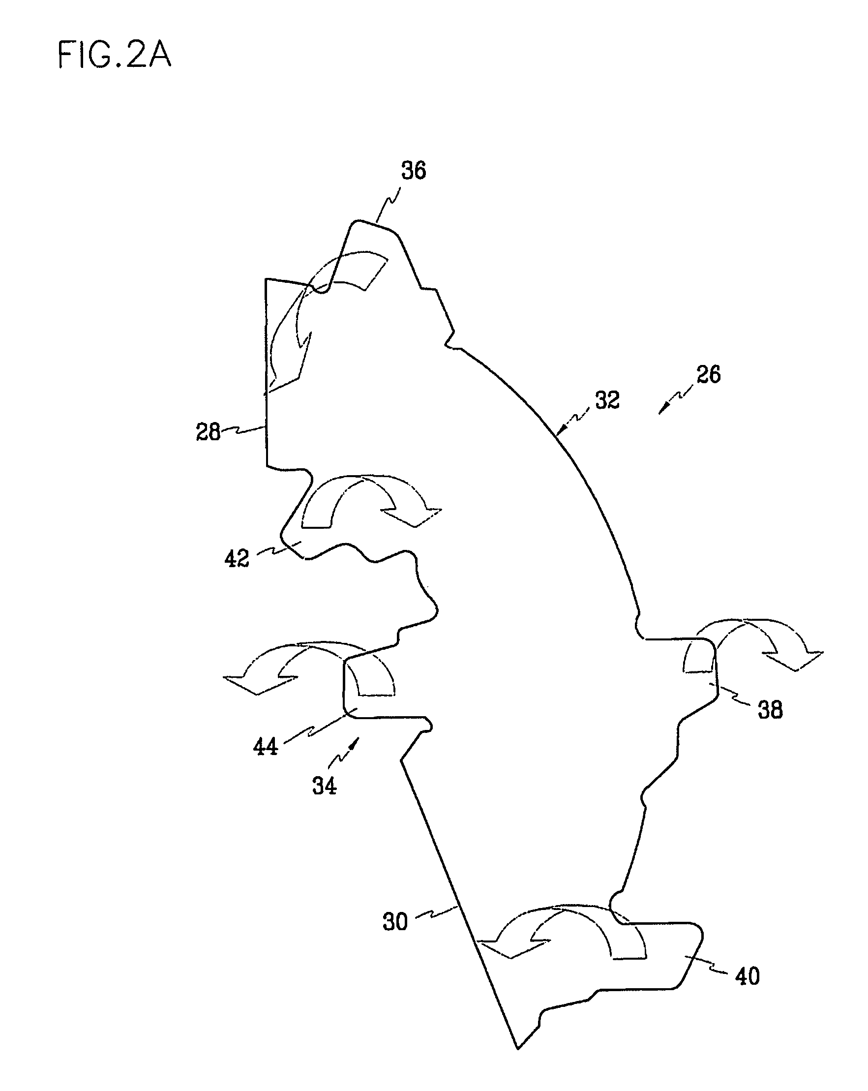
[0046] Each of the blades includes two straight line sections 28 and 30, an outer section contacting an inner surface of the shell 22, and an inner section contacting the core 24.
[0047] The outer section 32 is provided with outer projections 36, 38 and 40 coupled to the shell 22. The inner section 34 is provided with inner projections 34 coupled to the core 24.
[0048] The inner and outer projections 36, 38 and 40 and 42 and 44 are designed each having a size enough to penetrate slits (see FIG. 1) formed on the shell and core 22 and 24. Each of the inner and outer projections has a base 46 having a size identical to the slit and an extending section 48 extending from the base 46 and penetrating the slit.
[0049] Each extending section 48 of each projection is bent to closely contact the surface of the shell (or core), thereby maintaining the fixed state. That is, fixed state can be maintained by only bending the extending section 48. Particularly, in order to reduce the movement, the extending section is bent in an opposite direction to the adjacent extending section.
[0050] By doing this, the movement of the blades can be reduced.
[0051] In order to more securely fix the inner projections 42 and 44 of the blades 26 in the slits of the core 24, the slits of the core 24 are caulked after the projections are inserted therethrough.
[0052]FIG. 3 shows a retainer wear preventing unit according to an embodiment of the present invention.
[0053] As shown in FIG. 1, the retainer wear preventing unit is provided on a retainer 52 disposed between the turbine hub 16 and the one-way clutch 50 to restrict the movement of the one-way clutch in a direction of a shaft axis.
[0054] The retainer wear preventing unit of the present invention includes a seating groove 54 formed on the retainer 52 and a needle bearing 56 seated on the seating groove 54.
[0055] That is, a race 58 of the needle bearing 56 is located on the seating groove 54 and needle members 62 are located between the race 58 and the other race 60.
[0056] By the above-described structure, since the race 58 of the bearing is not rotated relative to the retainer 52 even when the turbine rotates, the wear of the retainer can be prevented.
[0057]FIG. 4 shows a retainer according to another embodiment of the present invention.
[0058] A retainer 52 of this embodiment is provided with a hole 64 to supply oil used as lubricant to a one-way clutch 50 through the hole 64. In order to more effectively supply the oil to the hole 64, an oil supplying groove 66 is formed on the retainer.
[0059] The oil supply groove 6 is formed extending from a setting hole 68 formed through a center of the retainer 52 in a radial direction.
[0060] In order to enhance the fluidity of the oil, the oil supplying groove 66 is formed in a circular arc shape. That is, a width of the oil supplying groove 66 is gradually reduced as it goes from an inlet of the groove 66 toward an outer side.
[0061] Accordingly, the oil to be supplied to the one-way clutch for the lubrication moves along the oil supplying groove 66, in the course of which the oil 64 is introduced toward the one-way clutch through the hole 64, thereby supply the oil enough to effectively operate the one-way clutch.
[0062] Since the enough oil operating the one-way clutch is supplied, the frictional heat generated by the frictional rotation can be discharged.
[0063] According to the present invention, by modifying the coupling structure of the blades to the turbine and impeller, the assembling property and the structural rigidity can be enhanced. Furthermore, since the retainer is provided with the seating groove for receiving the race of the needle bearing, the movement of the one-way clutch in the direction of the shaft axis can be prevented. In addition, by modifying the oil flow passage for directing the oil to the one-way clutch, the endurance of the torque converter can be improved.
[0064] It will be apparent to those skilled in the art that various modifications and variations can be made in the present invention. Thus, it is intended that the present invention covers the modifications and variations of this invention provided they come within the scope of the appended claims and their equivalents.

PUM

no PUM

Description & Claims & Application Information

We can also present the details of the Description, Claims and Application information to help users get a comprehensive understanding of the technical details of the patent, such as background art, summary of invention, brief description of drawings, description of embodiments, and other original content. On the other hand, users can also determine the specific scope of protection of the technology through the list of claims; as well as understand the changes in the life cycle of the technology with the presentation of the patent timeline. Login to view more.

Similar technology patents

Stretchable devices, display panels, sensors, and electronic devices

ActiveUS20210296599A1Prevent damage to and destructionEffectively applySolid-state devicesSemiconductor/solid-state device manufacturingPhysicsEngineering
Owner:SAMSUNG ELECTRONICS CO LTD

Classification and recommendation of technical efficacy words

Why Eureka
Try Eureka