Non-conductive fish tape

a non-conductive, fish tape technology, applied in the direction of cable installation apparatus, cable installation installation, electrical equipment, etc., can solve the problems of less steerability of the tape, increase the thickness of the tape, and not be suitable for use near live circuits with open contacts, etc., to achieve the effect of improving the adhesion, reducing the cost, and increasing the lubricity

Inactive Publication Date: 2006-03-30
POWER PROD
View PDF7 Cites 12 Cited by
  • Summary
  • Abstract
  • Description
  • Claims
  • Application Information

AI Technical Summary

Benefits of technology

[0013] The present invention is an improved non-conductive fish tape having a “flat” rectilinear tape construction providing strength, feedablity, steerability and windablity similarly to flat metal tapes but with lower cost, increased lubricity, lighter weight and without the risk of causing electrical shorting during use. Non-conductive end pieces of the fish tape are constructed to further these benefits.

Problems solved by technology

However, steel may be disadvantageous because it is heavy, possibly too rigid for tight bends, and importantly because it can conduct electricity, it may not be suitable for use near live circuits with open contacts, such as in switch boxes or fuse / breaker panels.
The circular cross-section is disadvantageous in that makes the fish tape less steerable and adds to its thickness such that it requires more space when wound in the reel.
However, it is not possible to bend fiberglass fish tapes to form a hook or loop.
The connection to the reel can be problematic.
The tape may disengage the catch, or worse, the tape may break when high pulling loads arise.
The latter problem can arise when the fiberglass tape is connected to reel in way that extends it radially relative to the reel.
When the fish tape is completely unwound from the reel and pulling loads are applied, a bending moment is applied to the fish tape which can cause it to fracture.
The tip at the leading end of the fish tape can also be problematic, most commonly with regard to its ability to feed through the wall or conduit and its connection to the fish tape.
Considerable effort has been undertaken to lessen the resistance in the feed direction, however, this still remains a problem.

Method used


Image

  • Non-conductive fish tape
  • Non-conductive fish tape
  • Non-conductive fish tape

Examples


Embodiment Construction

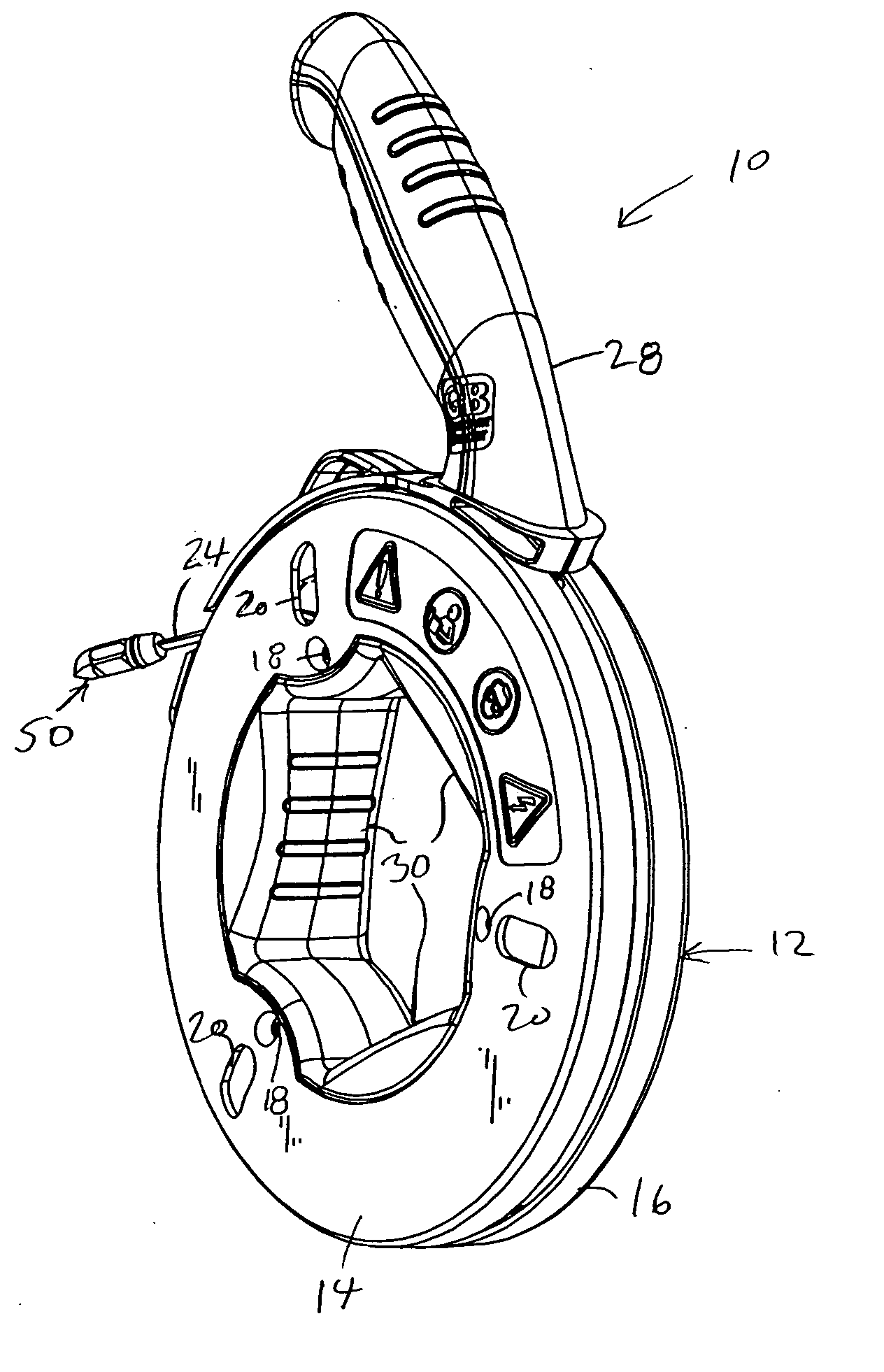
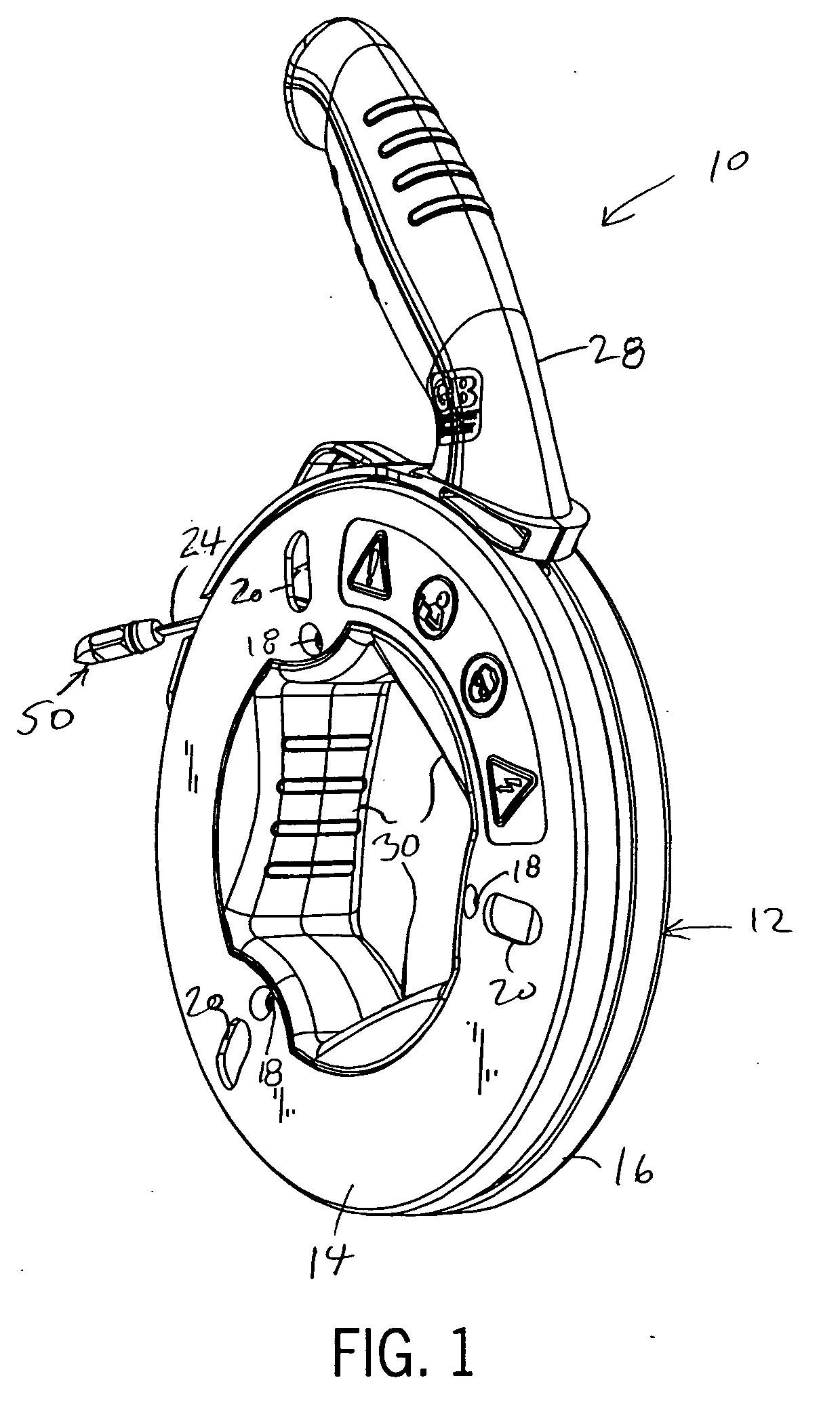
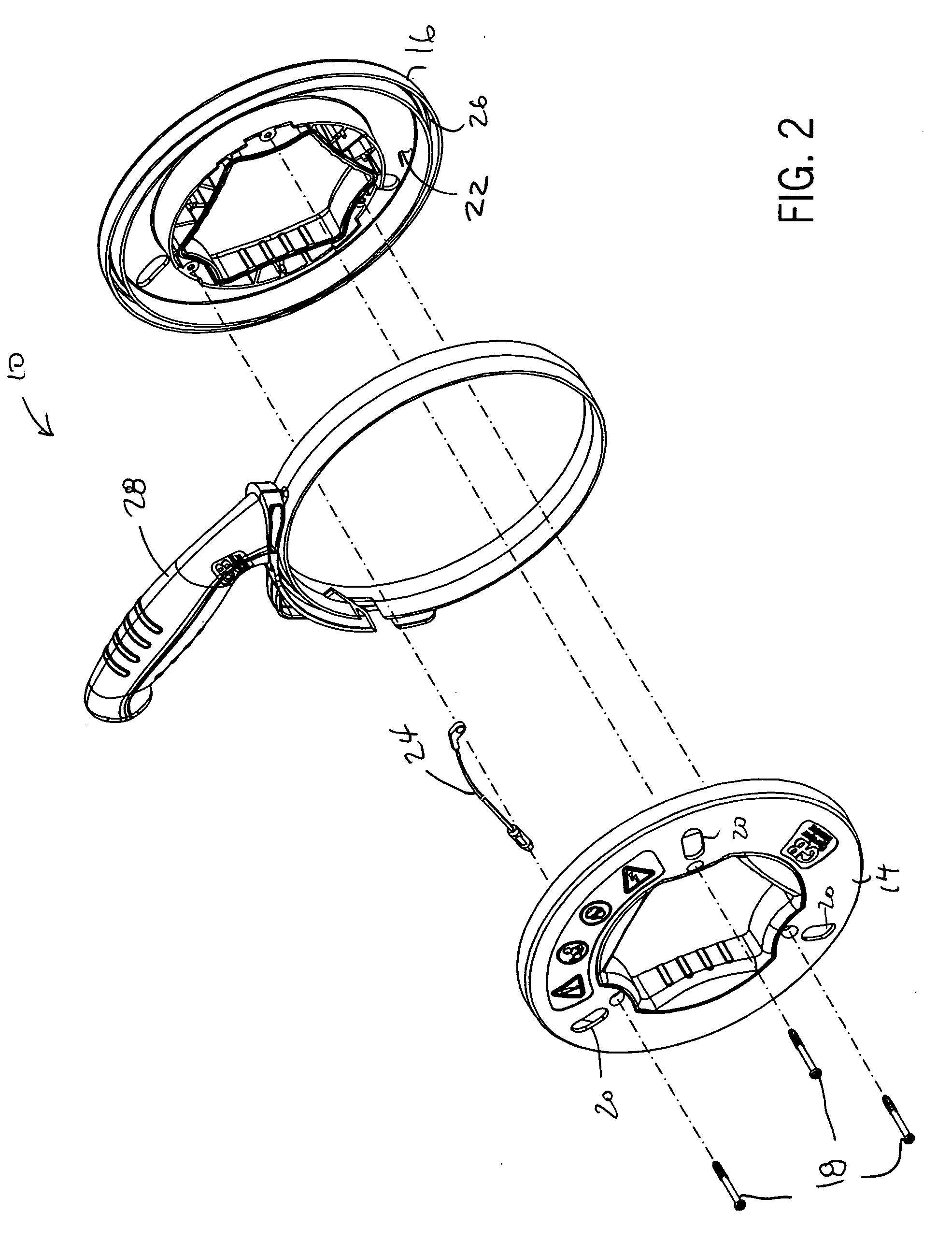
[0030] The drawings referenced herein illustrate a preferred version of a fish tape reel assembly 10. This reel assembly is preferred because of its durability and many ergonomic, and is described in detail in a co-pending PCT application filed on Aug. 6, 2004, entitled “Ergonomic Fish Tape” which claims priority to U.S. provisional application Ser. No. 60 / 493,819, filed on Aug. 8, 2003, the entire disclosure of which is incorporated by reference herein for its teaching on the construction, assembly and use of a preferred reel assembly for use with the fish tape of the present invention.

[0031] Briefly then, with reference to FIGS. 1-3, the reel assembly 10 includes a reel housing 12 having two annular housing parts 14 and 16 joined together by three angularly spaced fasteners 18, which are aligned with windows 20, to define an annular cavity 22 in which a length of fish tape 24 is wound. The reel housing parts 14 and 16 also define an annular groove 26, ringing the annular cavity 2...


PUM


Abstract

A fish tape assembly has a flat tape made of a hybrid composite of electrically non-conductive materials, preferably a fiberglass core surrounded by a nylon jacket. The flat tape has a rectilinear lateral cross-section with its width dimension being greater than its thickness. A non-conductive feed piece is bonded to the leading end of the fish tape. The feed piece has a wedged leading end. A non-conductive anchor piece is bonded to the trailing end of the fish tape to attach the fish tape to a reel assembly. The anchor piece is angled to mount the fish tape in a generally tangential direction relative to the reel.

Description

CROSS-REFERENCE TO RELATED APPLICATION [0001] This claims the benefit of U.S. Provisional Patent Application No. 60 / 614,931 filed Sep. 30, 2004.STATEMENT OF FEDERALLY SPONSORED RESEARCH OR DEVELOPMENT [0002] Not applicable. BACKGROUND OF THE INVENTION [0003] 1. Technical Field [0004] This invention relates to fish tapes of the type used by electricians to pull wire through conduit or other spaces, and more particularly to the construction of a non-conductive fish tape assembly. [0005] 2. Description of the Related Art [0006] A fish tape is an elongated “wire” or flexible rod typically used to install wire in conduit or through existing walls by pushing the tape through the conduit or wall, attaching the wire, and pulling it back. Steel fish tape is often used because it is stiff enough to be pushed through conduit without collapsing or kinking, flexible enough to negotiate bends or turns, and strong enough to pull multiple wires back through the conduit without breaking or separatin...

Claims


Application Information

Patent Timeline
Patent Type & Authority Applications(United States)
IPC IPC(8): H02G1/08
CPCB65H75/28B65H2701/376H02G11/02H02G1/085H02G1/083
Inventor RADLE, PATRICK J.BROCKMAN, DARYL C.HUEBSCHEN, DAVID A.
Owner POWER PROD
Why Eureka
Try Eureka