Multi-mode vibration generator for communication terminal

a communication terminal and multi-mode technology, applied in the direction of mechanical vibration separation, dynamo-electric machines, electrical apparatus, etc., can solve the problems of linear vibrators, inability to generate various vibrations, and inability to freely select the amount of vibrations, etc., to achieve excellent assembly, reduce the attachment area, and reduce the installation area

Inactive Publication Date: 2006-03-30
SAMSUNG ELECTRO MECHANICS CO LTD
View PDF12 Cites 19 Cited by
  • Summary
  • Abstract
  • Description
  • Claims
  • Application Information

AI Technical Summary

Benefits of technology

[0046] Another object of the present invention is to provide a multi-mode vibration generator for a communication terminal, which can be modularized so that its installation area is small and its assemblability is excellent.
[0047] Further another object of the present invention is to provide a multi-mode vibration generator for a communication terminal, which includes a PCB (printed circuit board) for reflow attachment and transmits a vibration by the PCB, thereby enabling minimization of an attachment area and modularlization.

Problems solved by technology

Therefore, the coin-type or the bar-type vibration motor cannot be adopted in a multimedia-functioned communication terminal that requires various patterned vibrations to be generated.
Besides, in case of the coin-type or the bar-type vibration motor, users cannot freely select the amounts of a vibration.
However, this linear vibrator also cannot generate various vibrations other than a vibration of predetermined direction.

Method used


Image

  • Multi-mode vibration generator for communication terminal
  • Multi-mode vibration generator for communication terminal
  • Multi-mode vibration generator for communication terminal

Examples


Embodiment Construction

[0069] Reference will now be made in detail to the preferred embodiments of the present invention, examples of which are illustrated in the accompanying drawings.

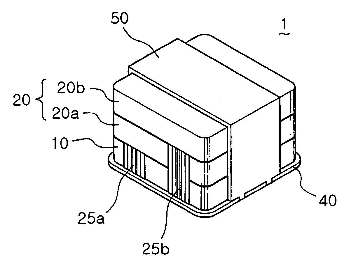
[0070]FIGS. 5A to 5C is a perspective view of a multi-mode vibration generator according to an embodiment of the present invention. FIG. 6 is an exploded perspective view of a multi-mode vibration generator according to an embodiment of the present invention. FIG. 7 is a sectional view of a multi-mode vibration generator according to an embodiment of the present invention. FIG. 8 is a plan view illustrating patterns of upper and lower parts of a PCB according to an embodiment of the present invention.

[0071] As shown in FIGS. 5A to 5C, the multi-mode vibration generator 1 according to the present invention includes a first vibration generator 10 and one or more second vibration generators 20.

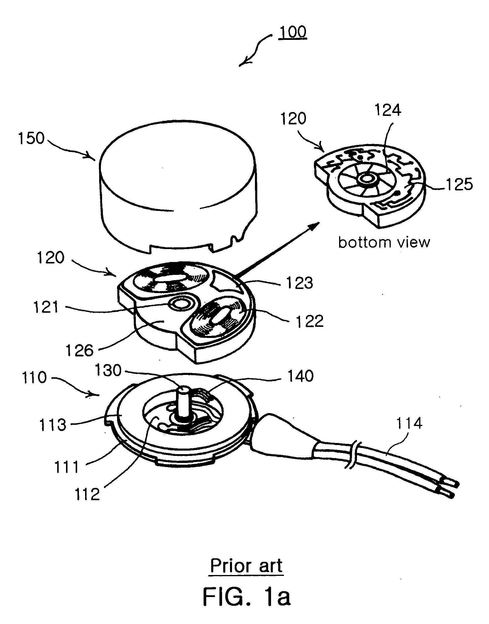
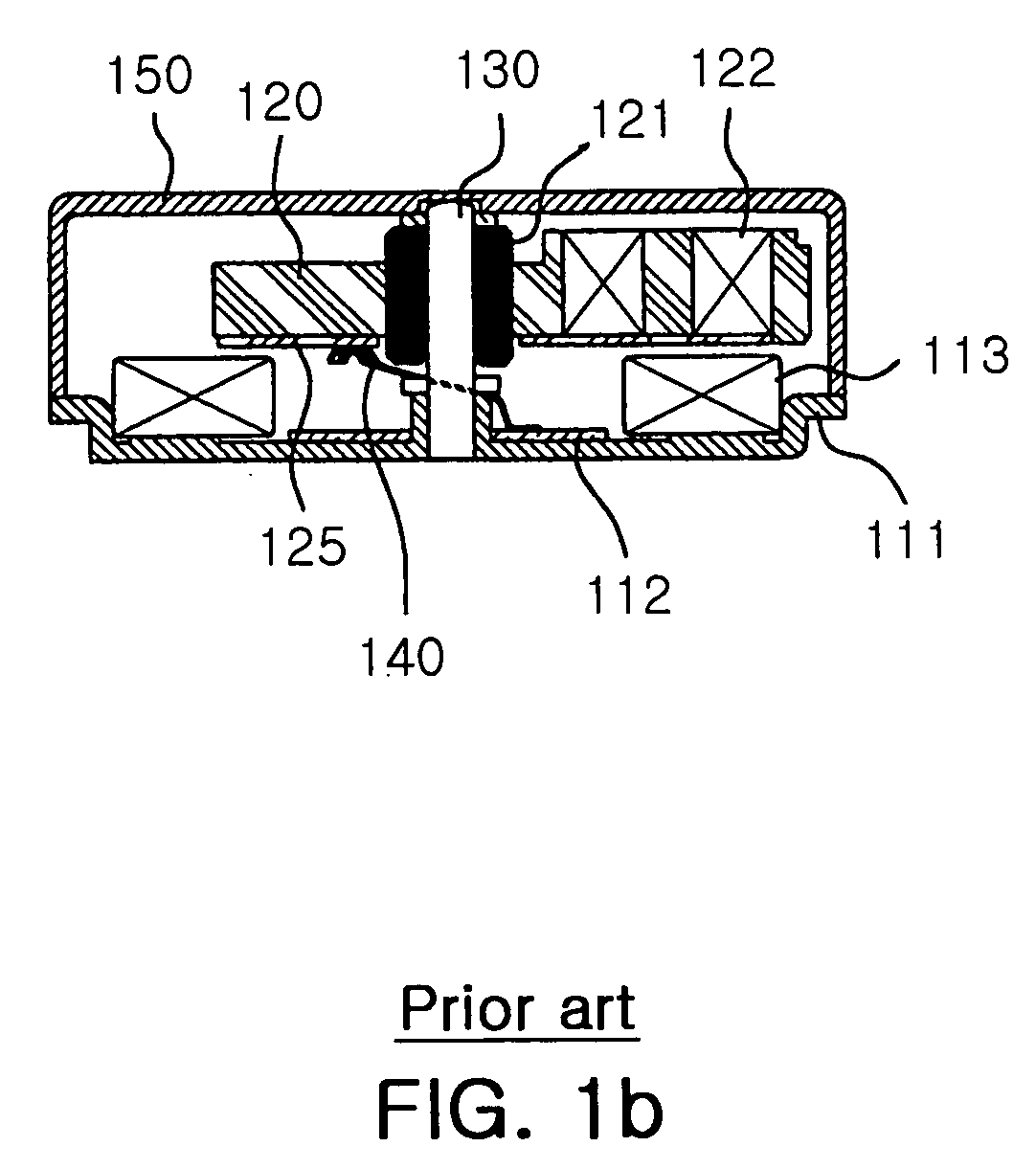
[0072] As the first vibration generator 10 and each of the second vibration generators 20, a coin-type vibration motor 100 and a hor...


PUM


Abstract

A multi-mode vibration generating device for a communication terminal includes a first vibration generator and one or more second vibration generators. The first vibration generator includes a first coil assembly and a first magnet and generating a vibration of a given direction by an interaction between an electric field generated by the first coil assembly and a magnet field generated by the first magnet. The one or more second vibration generators include a second coil assembly and a second magnet and generate a vibration of a given direction by an interaction between an electric field generated by the second coil assembly and an magnet field generated by the second magnet. The second vibration generator generates a vibration of a direction or frequency different from a vibration direction or frequency of the first vibration generator, whereby various mode vibrations are generated.

Description

RELATED APPLICATION [0001] The present application is based on, and claims priority from, Korean Application Number 2004-0077410, filed Sep. 24, 2004, the disclosure of which is hereby incorporated by reference herein in its entirety. BACKGROUND OF THE INVENITON [0002] 1. Field of the Invention [0003] The present invention relates to a device for generating various mode vibrations, and more particularly, to a device for generating various mode vibrations by stacking and modularizing two or more vibration generators whose vibration directions, amounts or frequencies are different from one another. [0004] 2. Description of the Related Art [0005] In general, one of essential functions of a communication terminal is an incoming call notification function. For functions frequently used as this incoming call notification function, there are a function of generating sounds such as a melody or a bell and a function of vibrating the terminal. [0006] Specifically, the vibrating function is ma...

Claims


Application Information

Patent Timeline
Patent Type & Authority Applications(United States)
IPC IPC(8): H02K7/06
CPCH02K7/063H02K7/061B06B1/12
Inventor KIM, JU HO
Owner SAMSUNG ELECTRO MECHANICS CO LTD
Why Eureka
Try Eureka