Ink container and mounting method of the ink container

a technology of ink containers and holder, which is applied in printing and other directions, can solve the problems of affecting the work efficiency the relative difficulty of engaging the guide recesses with the projections per se, and the liable large size of the recording apparatus, so as to reduce the working space above the holder required to mount the ink container

Inactive Publication Date: 2006-03-30
CANON KK
View PDF15 Cites 16 Cited by
  • Summary
  • Abstract
  • Description
  • Claims
  • Application Information

AI Technical Summary

Benefits of technology

[0022] As described above, according to the ink container and the mounting method thereof in the present invention, the main body of the ink container is provided with the guide portion for determining a mounting path of the ink container during mounting of the ink container at a side surface of the ink container main body. Further, the guide portion has the guide surface continuously extended over a predetermined length at a position where a part of the ...

Problems solved by technology

Particularly, the guide recesses have a relatively small width in a lateral direction thereof, so that there has arisen such a problem that it is rel...

Method used


Image

  • Ink container and mounting method of the ink container
  • Ink container and mounting method of the ink container
  • Ink container and mounting method of the ink container

Examples


first embodiment

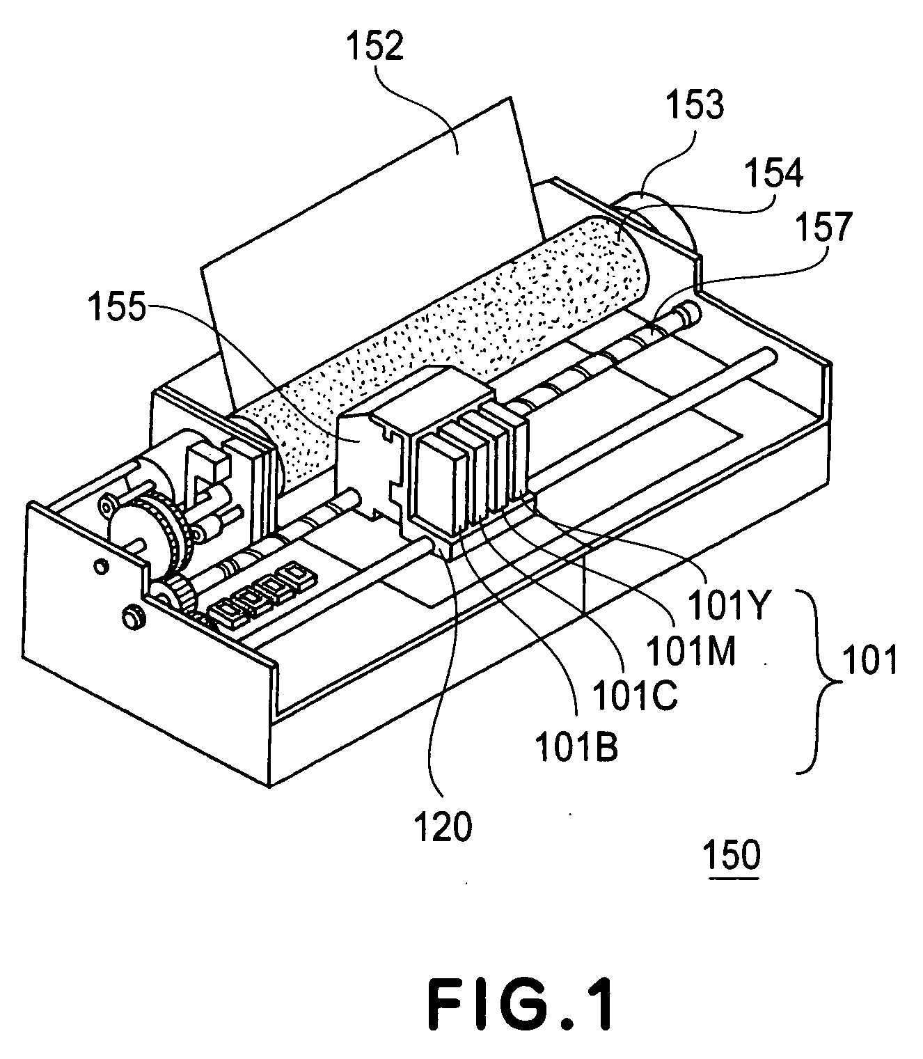
[0034] First, an example of an ink jet recording apparatus to which an ink container according to this embodiment will be described with reference to FIG. 1. FIG. 1 is a perspective view showing a constitution of the ink jet recording apparatus in this embodiment.

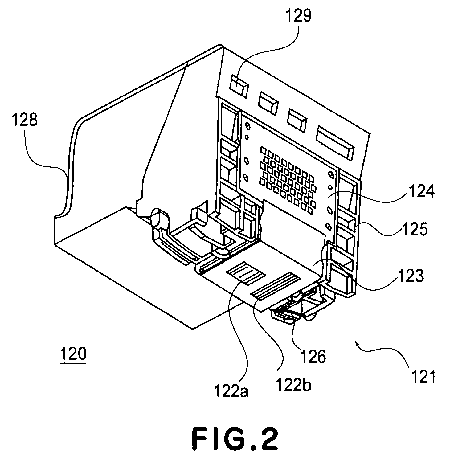
[0035] As shown in FIG. 1, an ink jet recording apparatus 150 includes a paper feed roller 154 for feeding a medium 152 to be recorded (simply referred to as “recording medium”), a head cartridge 120 for holding ink containers 101 of respective colors and ejecting ink to the recording medium 152, a carriage 120 for holding the head cartridge 120 and causing the head cartridge 120 to be reciprocally moved on the recording medium 120 in a width direction of the recording medium 120. Incidentally, the ink jet recording apparatus 150 is used at a position such that the ink containers 101 are located in front of the recording apparatus 150 when viewed from a user.

[0036] The paper feed roller 154 is, more specifically, constitu...

second embodiment

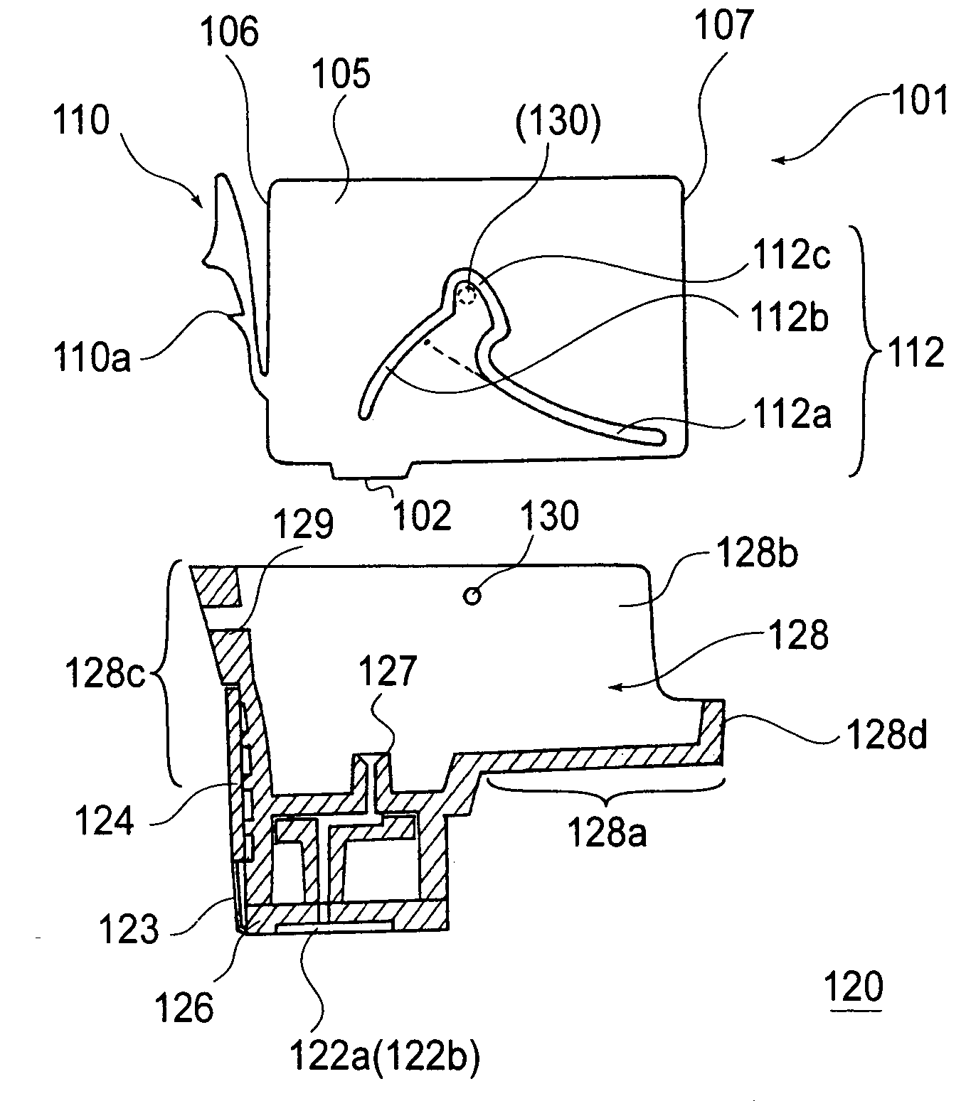
[0066] Second Embodiment of the ink container according to the present invention will be described with reference to FIGS. 6(a) to 6(d). FIGS. 6(a) to 6(d) are sectional views showing a constitution of the ink container in this embodiment and another example of a sequence of steps of mounting the ink container 111. The ink container 111 shown in FIGS. 6(a) to 6(d) has the same constitution as the ink container 101 of First Embodiment except that the shape of the guide portion 112 of the ink container 101 of First Embodiment is modified. Further, the head cartridge 120 shown in FIGS. 6(a) to 6(d) is identical to that of First Embodiment. The ink container 111 of this embodiment include a guide portion 113 as shown in FIG. 6(d). More specifically, the guide portion 113 is provided with a first inclined portion 112a and a second inclined portion 112b which have the substantially same shapes as those provided to the ink container 101 of First Embodiment and is provided with a vertical g...

third embodiment

[0074] The head cartridges 120 described in First and Second Embodiments are, as shown in FIG. 3, the lower right corners of the ink containers 101 and 111 are held by the front holding portion 128a extended to the front (the right side on the drawing) of the head cartridge 120 but in this embodiment, the shape of the front holding portion is modified as shown in FIG. 8.

[0075] Referring to FIG. 8, a head cartridge 140 is provided with a front holding portion 128e which is formed in a shorter length than that of the head cartridge 120 shown in FIG. 3 by being cut largely on its front side. Incidentally, an ink container 101 shown in FIG. 8 is identical to that of First Embodiment shown in FIG. 3. FIG. 8 shows a state wherein a sliding projection 130 of the head cartridge contacts the second inclined portion 112b.

[0076] In the case where the ink container 101 is mounted in the thus constituted head cartridge 140, as shown in FIG. 8, the lower right corner of the ink container 101 is...


PUM


Abstract

An ink container capable of being simply mounted in a holder with a small working space includes a rib-like guide portion for determining a mounting path during mounting of the ink container in a head cartridge at a side surface. The head cartridge includes a holder portion provided with a sliding projection which slides in contact with the guide portion. When the ink container is mounted, a user moves the ink container so that a first inclined portion first contacts the sliding projection and thereafter the ink contained is moved in an obliquely below direction toward the head cartridge while sliding the sliding projection along the first inclined portion.

Description

FIELD OF THE INVENTION AND RELATED ART [0001] The present invention relates to an ink container constituted detachably mountable to a holder and a method of mounting the ink container. [0002] Heretofore, recording apparatuses for effecting recording with respect to a medium to be recorded such as paper, cloth, a plastic sheet, an OHP sheet, or the like (hereinafter, simply referred to as “recording paper”) have been proposed as those to which a recording head of various recording modes, such as a wire dot mode, a heat-sensitive mode, a thermal transfer method, and an ink jet recording mode is mountable. Of these recording modes, the ink jet recording mode is a nonimpact mode in which ink is ejected from an ejection outlet (nozzle) onto the recording paper and is known as a mode capable of performing a high-density and high-speed recording operation with low noise. Further, the ink jet recording apparatus also has the advantages such that it has low running costs, can be reduced in a...

Claims


Application Information

Patent Timeline
IPC IPC(8): B41J2/175
CPCB41J2/1752
Inventor MATSUMOTO, NOBUYUKIKANEKO, HAJIME
Owner CANON KK
Why Eureka
Try Eureka