Single reflective light valve projection device

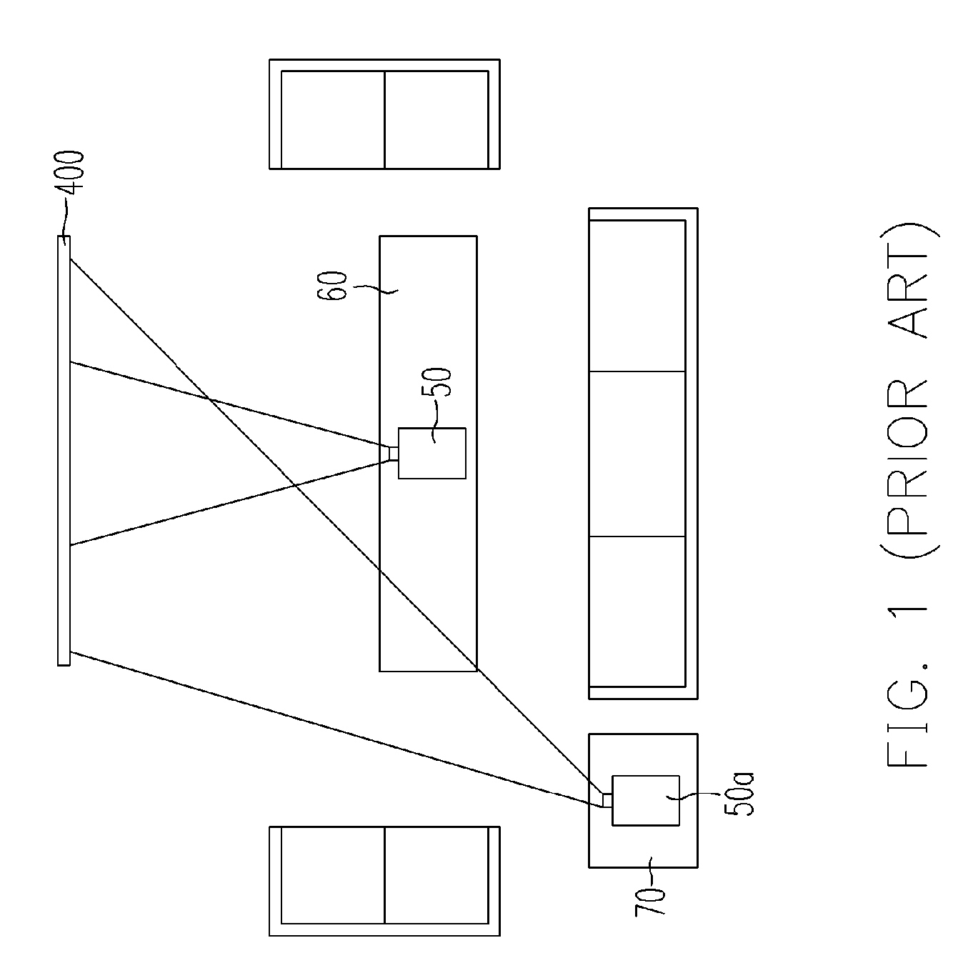
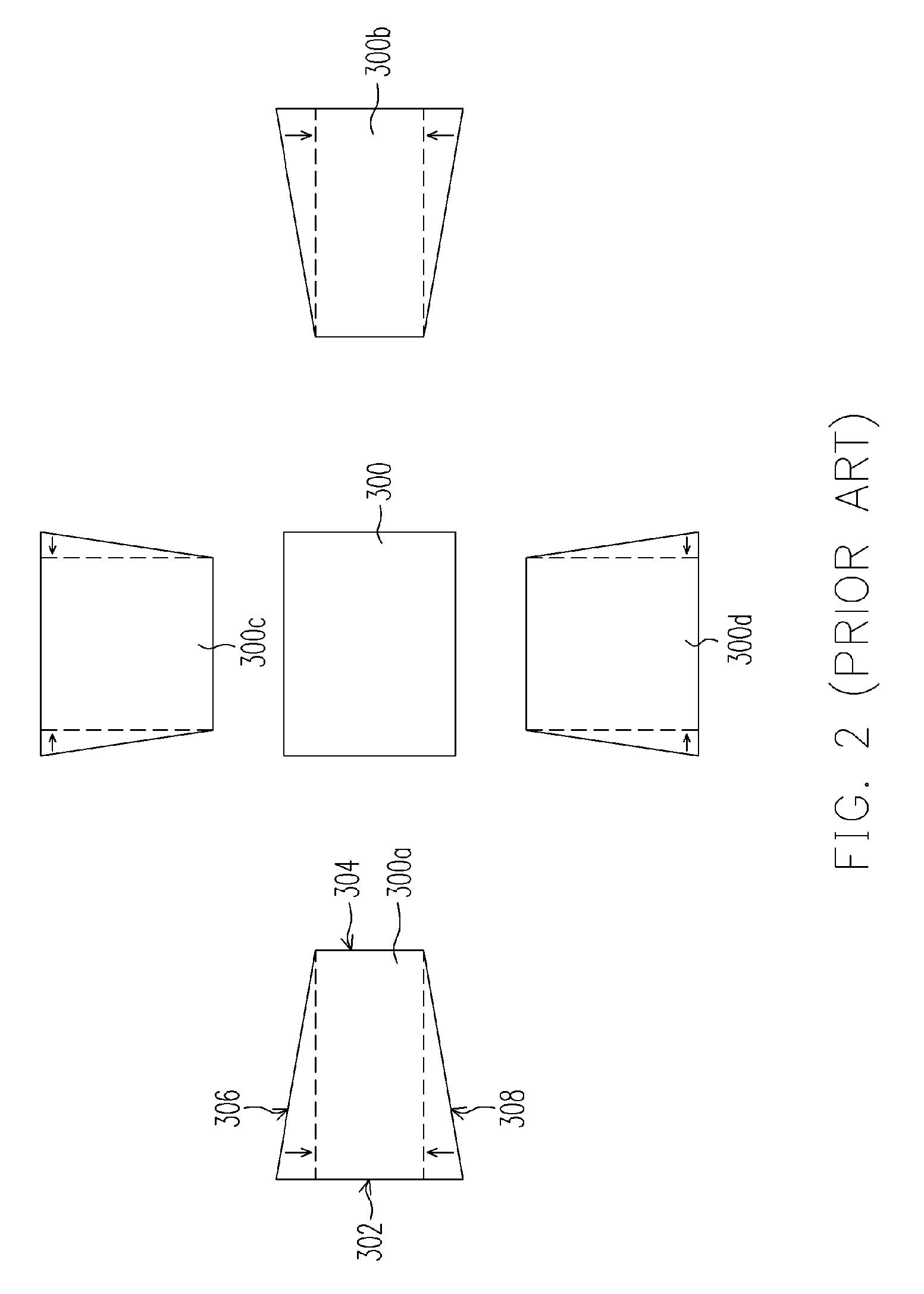
a projection device and reflective light technology, applied in the direction of projectors, optics, instruments, etc., can solve the problems of device b>50/b> being pulled onto the floor and smashed, user walking across to fall down, image distortion, etc., and achieve the effect of high image projection property

Inactive Publication Date: 2006-03-30
AIXIN TECH
View PDF3 Cites 10 Cited by
  • Summary
  • Abstract
  • Description
  • Claims
  • Application Information

AI Technical Summary

Benefits of technology

[0021] The present invention is to provide a low-cost single reflective light valve projection device capable of side pr

Problems solved by technology

However, the projection device 50 has a power cable and other signaling lines, which might cause users walking across to fall down, or the projection device 50 can be pulled onto the floor and smashed.
Furthermore, the corrected image will produce distorted electrical signals such as a toothed shape, and ultimately lead to image distortion.
Although this method of adjustment will not lead to problems such as image distortion, a distortion of electrical signals, a reduced image size or lower brightness level, however, the projection lens must cover the reflective light valve and its offset range and thus a larger projection lens is r

Method used


Image

  • Single reflective light valve projection device
  • Single reflective light valve projection device
  • Single reflective light valve projection device

Examples


first embodiment

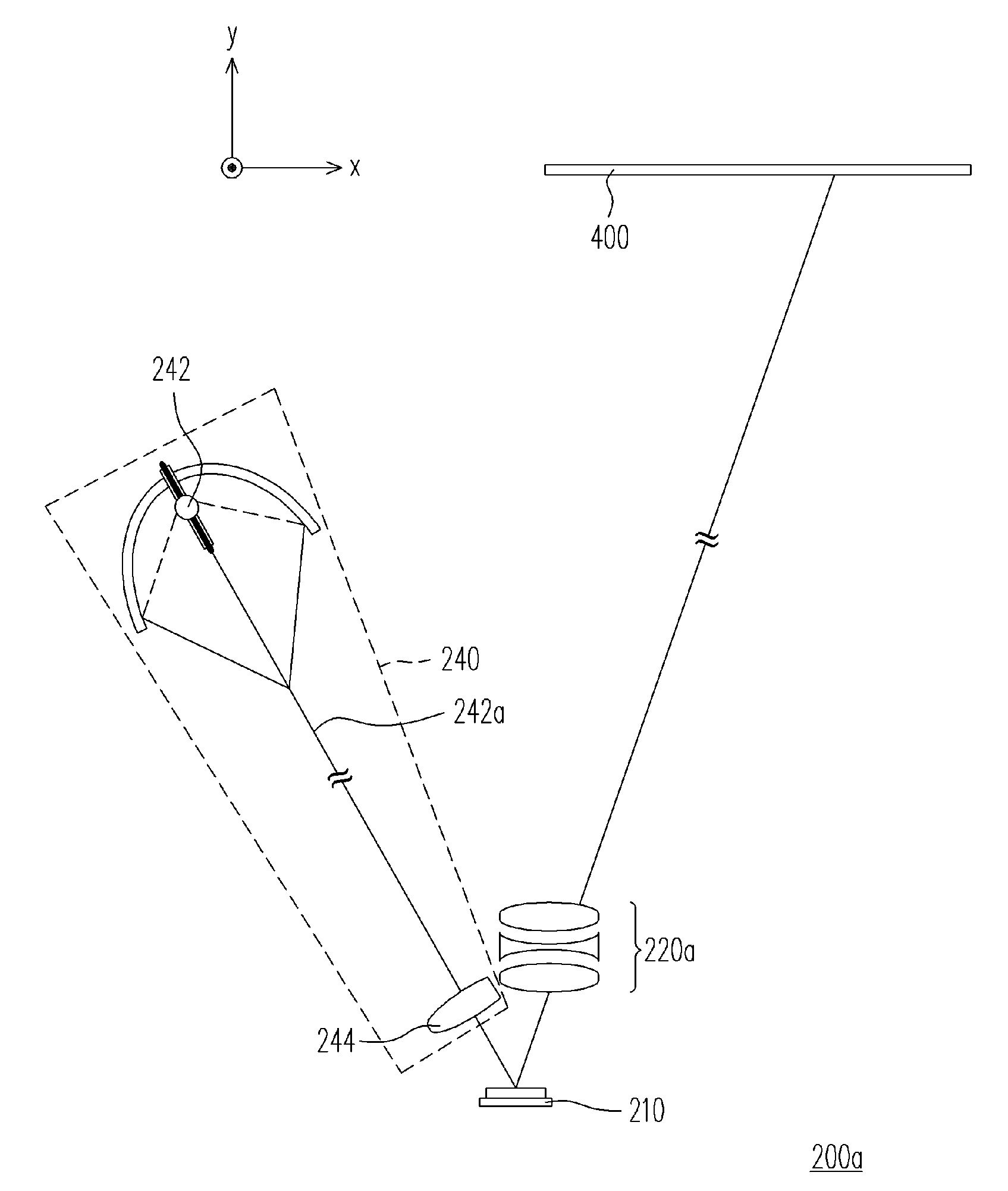
[0046]FIG. 8 is a diagram showing the structure of a single reflective light valve projection device according to a first embodiment of the present invention. FIG. 9 is a drawing showing the relative positions of the reflective light valve, the lens and the projection lens inside a single reflective light valve projection device according to the first embodiment of the present invention. As shown in FIGS. 8 and 9, the present embodiment provides a single reflective light valve projection device 200a suitable for performing side projection along a horizontal line (an X-axis). The single reflective light valve projection device 200a includes a non-telecentric illumination system 240, a projection lens 220a and a reflective light valve 210. The non-telecentric illumination device 240 further includes a light source 242 and a lens 244.

[0047] In the aforementioned single reflective light valve projection device 200a, the light source 242 provides a light beam 242a and the lens 244 is di...

second embodiment

[0052]FIG. 11 is a diagram showing the structure of a single reflective light valve projection device according to a second embodiment of the present invention. FIG. 12 is drawing showing the relative positions of the reflective light valve, the lens and the projection lens inside a single reflective light valve projection device according to the second embodiment of the present invention. As shown in FIGS. 11 and 12, the present embodiment provides a single reflective light valve projection device 200b capable of performing side projection along a horizontal line (X-axis) and / or a vertical line (Z-axis). The single reflective light valve projection device 200b includes a non-telecentric illumination system 240, a projection lens 220b and a reflective light valve 210. The non-telecentric illumination system 240 further includes a light source 242 and a lens 244.

[0053] In the single reflective light valve projection device 200b, the light source 242 provides a light beam 242a and th...


PUM


Abstract

A single reflective light valve projection device comprising a non-telecentric lighting system, a projection lens and a reflective light valve is provided. The non-telecentric lighting system comprises a light source and a lens. The light source provides a light beam. The lens is disposed in the transmission path of the light beam. The projection lens is disposed behind the lens and in the transmission path of the light beam. The reflective light valve is disposed between the lens of the non-telecentric lighting system and the projection lens and in the transmission path of the light beam. The reflective light valve comprises many horizontally aligned rows of pixels. A line joining the center of the projection lens to the center of the lens forms an angle smaller than π/4 with respect to a horizontal line to provide side projection in the horizontal direction.

Description

CROSS-REFERENCE TO RELATED APPLICATION [0001] This application claims the priority benefit of Taiwan application serial no. 93129184, filed on Sep. 27, 2004. All disclosure of the Taiwan application is incorporated herein by reference. BACKGROUND OF THE INVENTION [0002] 1. Field of the Invention [0003] The present invention relates to a projection device having a single reflective light valve. More particularly, the present invention relates to a single reflective light valve projection device with low cost and suitable for side projection. [0004] 2. Description of the Related Art [0005] In recent years, bulky and heavy cathode ray tube (CRT) projection devices have been gradually replaced by LCD projectors and digital light processing (DLP) projectors. These products are not only light and portable, but also can be directly connected with other digital products to display images. With the fierce competition among manufacturers, many cheap projectors having a variety of additional f...

Claims


Application Information

Patent Timeline
IPC IPC(8): G03B21/28
CPCG03B21/28
Inventor WANG, SHEN-HUEILIN, TZUNG-IWANG, SZE-KE
Owner AIXIN TECH
Why Eureka
Try Eureka