Heat sink module

a heat sink and module technology, applied in the direction of cooling/ventilation/heating modification, semiconductor/solid-state device details, semiconductor devices, etc., can solve the problems of inability to maximize performance, electronic products cannot be stable, and heat dissipation issue becomes a serious problem, so as to enhance the heat dissipation effect and dissipate heat

Inactive Publication Date: 2007-03-22
GRAND POWER SOURCES
View PDF3 Cites 54 Cited by
  • Summary
  • Abstract
  • Description
  • Claims
  • Application Information

AI Technical Summary

Benefits of technology

[0009] In view of the shortcomings of the prior art, the inventor of the present invention based on years of experience to conduct extensive researches and experiments, and finally invented a heat sink module capable of conducting heat and dissipating heat to the outside quickly as to enhance the heat dissipating effect.
[0010] Therefore, it is a primary objective of the present invention to provide a heat sink module comprising a base, and the base comprises a base member and a thermal conductive frame. The base member comprises a plurality of graphite layers with a plane having a high thermal conductivity property, and the base member includes an insert received at an appropriate position of a cavity. The insert is comprised of a graphite compound conducting heat in a direction perpendicular to the base member, an isotropic thermal conductive metal compound, a thermal conductive composite that its thermal conductive filler produces a phase change due to heat, or a combination of the abovementioned composites. Further, the base member is closely sealed by a thermal conductive frame, and the base has a heat dissipating fin set, such that when the heat sink module is in use, the inserts are attached directly onto the core of a heat source to conduct heat from the inserts. When the inserts are conducting heat, the heat is conducted from the base at the periphery of the insert along its plane, and then from the base member to the thermal conductive frame, and finally dissipated to the outside via fin set in a quick manner. Therefore, the invention not only reduces the weight of the whole heat sink module by using a thermal conductive material such as a graphite composite to make the base, but also overcomes the shortcoming of having heat remained on the base.

Problems solved by technology

In recent years, electronic products tend to be packed in a high density and developed with multifunction, so that the heat dissipating issue becomes a serious problem.
If electronic components do not have a proper heat dissipating policy, then the performance cannot be maximized, or in a more serious case, the electronic products will not be stable due to the sudden increase of temperature inside the machine.
However, an increase of volume will increase the weight.
More particularly, electronic products tend to be light, thin, short, and compact, and it is obvious that the internal space provided by electronic products for dissipating heat is insufficient.
The increase in weight of the heat sink may press and damage electronic components or have other adverse effects.
Therefore, the heat cannot be dissipated to the outside quickly by the heat dissipating fins.
As a result, the heat remains at the planar element 100 and causes damages to the electronic component or even a system crash.

Method used


Image

  • Heat sink module
  • Heat sink module
  • Heat sink module

Examples


Embodiment Construction

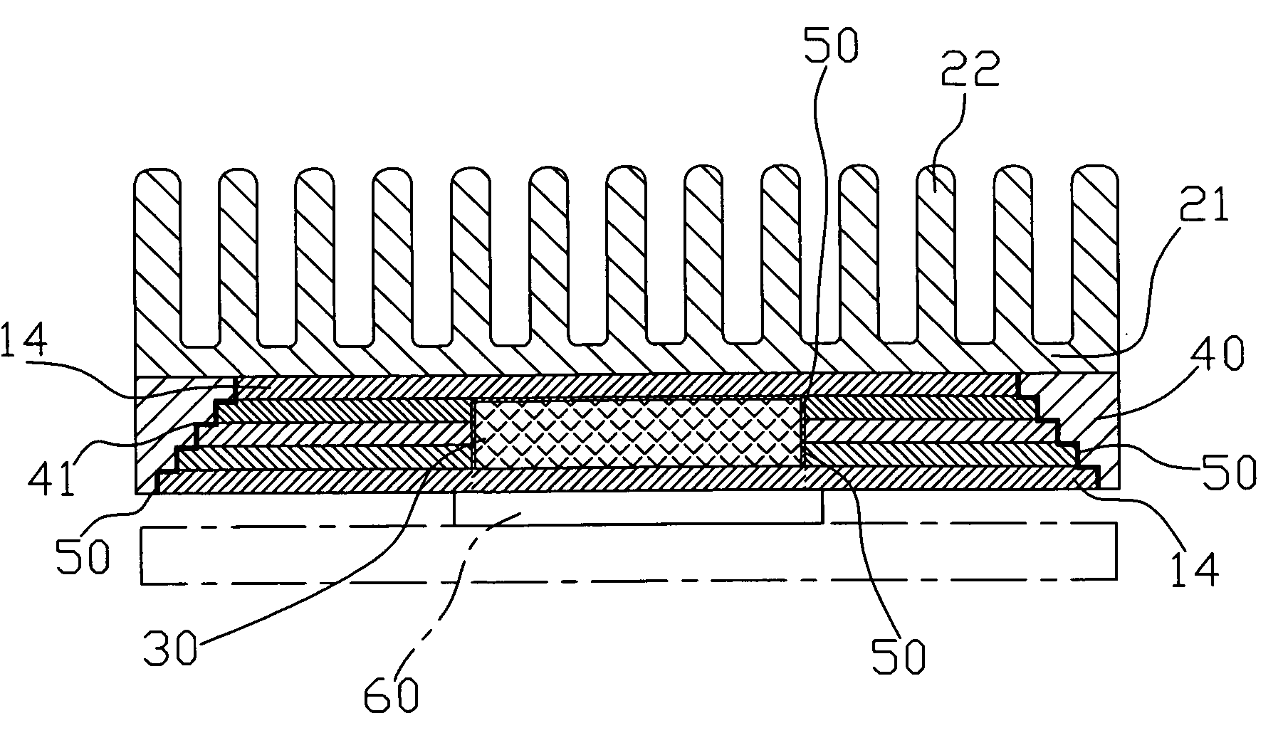
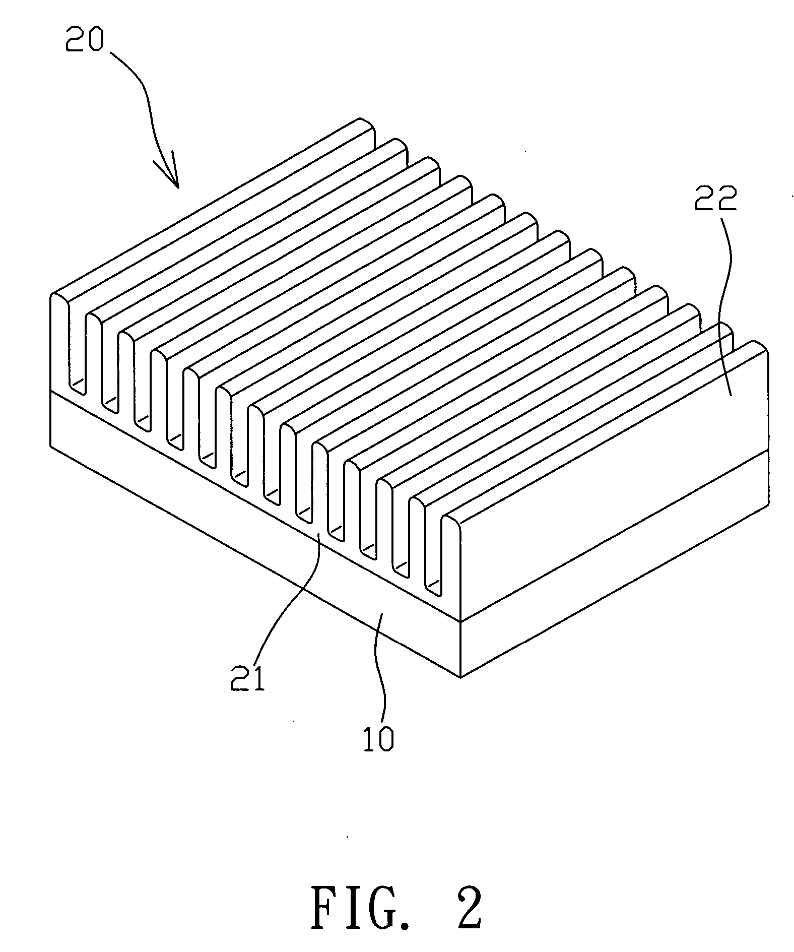
[0024] Referring to FIGS. 2 to 5 for the heat sink module of a preferred embodiment of the present invention, a base 10 comprises a heat dissipating fin set 20 thereon, and the heat dissipating fin set 20 includes a bottom 21 thereon, which is a slab for this embodiment, and the bottom 21 includes a plurality of fins 22 arranged neatly with each other.

[0025] The base 10 comprises a base member 11 and a hollow thermal conductive frame 40, and the base member 11 comprises a plurality of graphite layers 12 having a high thermal conductivity on its planar direction, and the area of the graphite layers 12 becomes increasingly smaller from the bottom to the top like a stairway shape, and the base member 11 has a cavity 13 disposed at an appropriate position for penetrating all graphite layers 12, and an insert 30 is received in the cavity 13. The insert 30 of this preferred embodiment is a coiled graphite sheet filled with a phase-change thermal conductive material (however, the persons ...


PUM

PropertyMeasurementUnit
thermal conductivityaaaaaaaaaa
thermal conductiveaaaaaaaaaa
heat conductiveaaaaaaaaaa

Abstract

A heat sink module includes a base having a metal heat dissipating fin set, and the base includes a planar base member comprised of a plurality of graphite layers, and said planar base member embeds a vertical insert having a high thermal conductivity, and the insert comprises a graphite compound disposed vertically with the base member for conducting heat or an isotropic thermal conductive metal compound, or a thermal conductive material compound that produces a phase change by heat, and the base member includes a thermal conductive frame having an isotropic high thermal conductivity and disposed at the periphery, and the thermal conductive frame and the base member are combined to form a heat dissipating base. When the heat sink module is in use, the area proximate to the inserts is attached to the core of a heat source core, so that the inserts can absorb and conduct the heat produced by the heat source quickly. Since the graphite layer is anisotropic when conducting heat, therefore the heat is conducted from the periphery to the thermal conductive frame by the horizontal graphite layer when the heat is conducted to the insert, and then the heat is dissipated to the outside via the thermal conductive frame quickly by the heat dissipating fin.

Description

BACKGROUND OF THE INVENTION [0001] 1. Field of the Invention [0002] The present invention relates to a heat sink module, and more particularly to a heat sink module including a base member made of a graphite layer with a high thermal conductivity along a planar direction, an insert embedded vertically onto the planar base member and having a high thermal conductivity, and a thermal conductive frame having an isotropic high thermal conductivity, such that the heat can be conducted quickly from the heat source from the insert through the base member, and the heat is dispersed from the conductive frame to the periphery and the outside, and thus the heat will not remain on the heat source. [0003] 2. Description of the Related Art [0004] In recent years, electronic products tend to be packed in a high density and developed with multifunction, so that the heat dissipating issue becomes a serious problem. If electronic components do not have a proper heat dissipating policy, then the perfo...

Claims


Application Information

Patent Timeline
Patent Type & Authority Applications(United States)
IPC IPC(8): H05K7/20
CPCH01L23/3675H01L2924/0002H01L2924/00
Inventor YAO, PEI-CHIH
Owner GRAND POWER SOURCES
Why Eureka
Try Eureka