Piezoelectric oscillator and piezoelectric oscillation device

a piezoelectric oscillator and piezoelectric technology, applied in the direction of oscillator, semiconductor device, electrical apparatus, etc., can solve the problems of hindering the adjustment of the integrated circuit element, the heat generated by the integrated circuit element may not be easily released to the outside of the oscillator, etc., to achieve the effect of dissipating heat, easy and effective dissipation of heat to the outside, and easy and effective dissipation of heat generated by

Active Publication Date: 2021-12-14
MURATA MFG CO LTD
View PDF18 Cites 0 Cited by
  • Summary
  • Abstract
  • Description
  • Claims
  • Application Information

AI Technical Summary

Benefits of technology

[0006]The exemplary embodiments of the present disclosure have been made in consideration of the above circumstances. Thus, it is an object thereof to provide a piezoelectric oscillator and a piezoelectric oscillation device that can easily and effectively dissipate heat that is generated by an electronic component.
[0008]With the structure described above, the first heat conduction portion, which is disposed in a space in which the electronic component is disposed, can absorb heat from the electronic component, and the second heat conduction portion can dissipate the heat to the outside. Therefore, heat that is generated by the electronic component can be easily and effectively dissipated to the outside.
[0010]With the structure described above, the first heat conduction portion, which is disposed in the gap that is connected to the space in which the electronic component is disposed, can absorb heat from the electronic component, and the second heat conduction portion can dissipate the heat to the outside. Therefore, heat that is generated by the electronic component can be easily and effectively dissipated to the outside.
[0012]With the structure described above, the first heat conduction portion, which is disposed in the space in which the electronic component is disposed, can absorb heat from the electronic component, and the second heat conduction portion can dissipate the heat to the outside. Therefore, heat that is generated by the electronic component can be easily and effectively dissipated to the outside.
[0013]With the exemplary aspects of the present invention, a piezoelectric oscillator and a piezoelectric oscillation device are provided that can easily and effectively dissipate heat to the outside that is generated by an electronic component.

Problems solved by technology

With such an existing structure as shown in Patent Document 1, because the integrated circuit element is disposed on the circuit board in a space surrounded by the mounting frame, heat that is generated by the integrated circuit element may not be easily released to the outside of the oscillator.
The temperature difference may hinder the integrated circuit element from performing adjustment of temperature control and adjustment of frequency variation of the quartz crystal element.

Method used


Image

  • Piezoelectric oscillator and piezoelectric oscillation device
  • Piezoelectric oscillator and piezoelectric oscillation device
  • Piezoelectric oscillator and piezoelectric oscillation device

Examples


Embodiment Construction

[0022]Hereinafter, exemplary embodiments of the present disclosure will be described. In the drawings used in the following description, elements that are the same as or similar to each other are denoted by the same or similar numerals. The drawings show examples, and the dimensions and shapes of elements in the drawings are schematic. It should be noted that the technical scope of the exemplary aspects of the present invention is not limited to the embodiments described below.

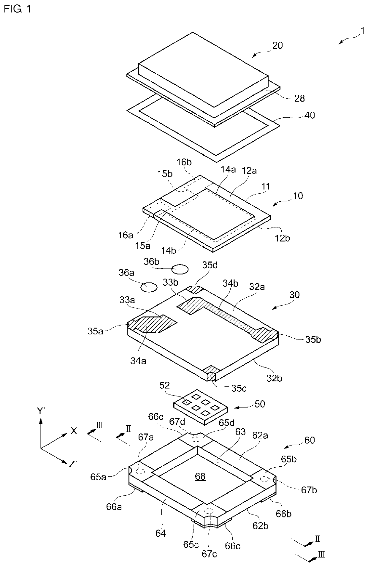
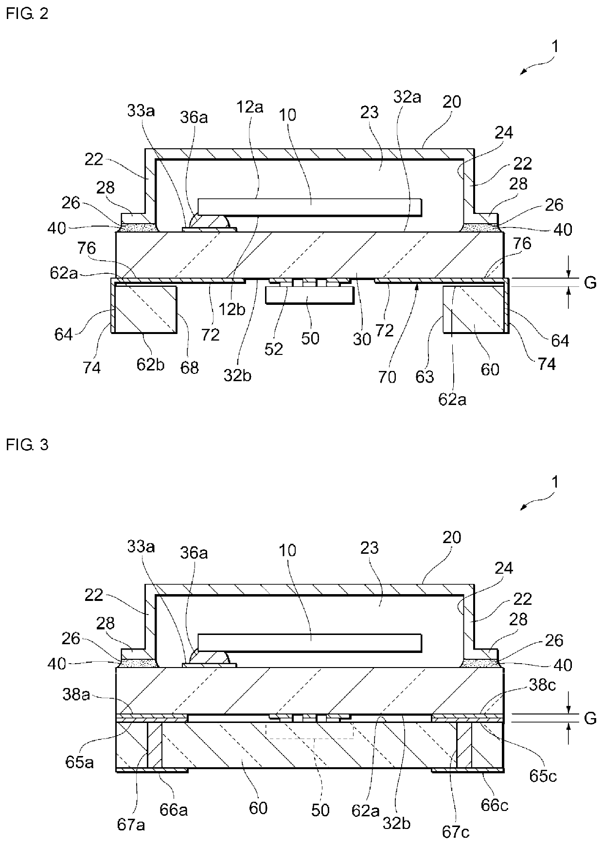
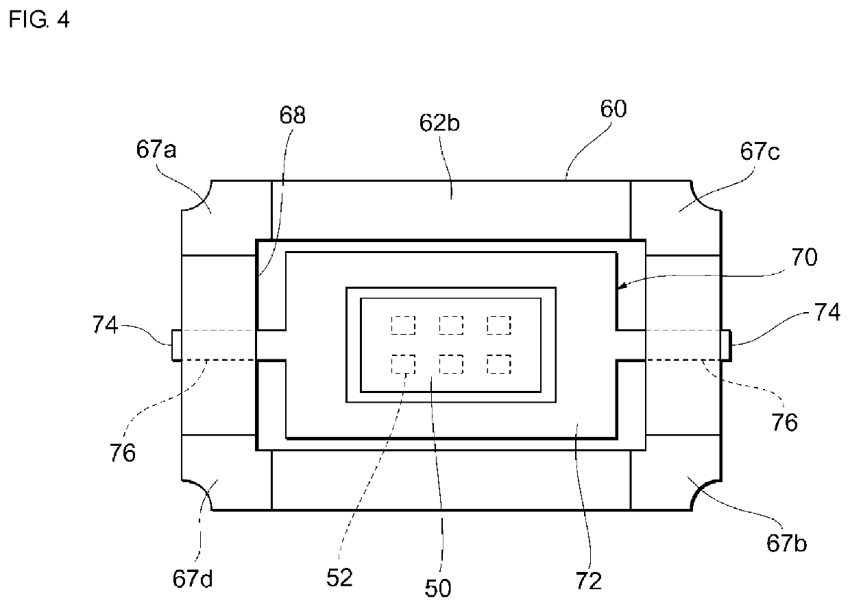
[0023]Referring to FIGS. 1 to 3, a piezoelectric oscillator according to an exemplary embodiment will be described. FIG. 1 is an exploded perspective view of the piezoelectric oscillator, FIG. 2 is a sectional view taken along line II-II of FIG. 1, and FIG. 3 is a sectional view taken along line III-III of FIG. 1. In FIGS. 2 and 3, electrodes of the piezoelectric resonator are not illustrated.

[0024]As illustrated in FIG. 1, a piezoelectric oscillator 1 according to the present embodiment includes a piezoelectr...


PUM


Abstract

A piezoelectric oscillator includes a base member; a piezoelectric resonator mounted on an upper surface of the base member; a lid member joined to the upper surface so as to hermetically seal the piezoelectric resonator; an electronic component mounted on a lower surface of the base member; a mounting frame joined to the lower surface so as to surround the electronic component; and a heat conduction path disposed on the base member and / or the mounting frame. The heat conduction path is electrically isolated from both of the piezoelectric resonator and the electronic component in the piezoelectric oscillator and has heat conductivity. The heat conduction path includes a first heat conduction portion inside where the base member and the mounting frame overlap, and a second heat conduction portion connected to the first heat conduction portion and disposed outside where the base member and the mounting frame overlap.

Description

CROSS REFERENCE TO RELATED APPLICATIONS[0001]The present application is a continuation of PCT / JP2016 / 073528 filed Aug. 10, 2016, which claims priority to Japanese Patent Application No. 2015-217936, filed Nov. 5, 2015, the entire contents of each of which are incorporated herein by reference.TECHNICAL FIELD[0002]The present disclosure relates to a piezoelectric oscillator and a piezoelectric oscillation device.BACKGROUND[0003]Patent Document 1 (identified below) describes, as a type of piezoelectric oscillation device, a quartz crystal oscillator in which a quartz crystal element is disposed on an upper surface of a substrate, an electronic component (such as an integrated circuit element) is formed on a lower surface of the substrate, and the integrated circuit element is surrounded by a mounting frame. The quartz crystal oscillator is mounted on a circuit board in such a way that the mounting frame faces the circuit board.[0004]Patent Document 1: Japanese Unexamined Patent Applica...

Claims


Application Information

Patent Timeline
Patent Type & Authority Patents(United States)
IPC IPC(8): H03B5/32H03H9/19H03H9/10H03H9/02H03H9/05H03B5/04
CPCH03B5/32H03B5/04H03H9/02102H03H9/0538H03H9/0552H03H9/1021H03H9/19H01L2224/16225H01L2924/16152
Inventor NOTO, KAZUYUKI
Owner MURATA MFG CO LTD
Why Eureka
Try Eureka