
Backlight module and mobile terminal
a backlight module and mobile terminal technology, applied in the field of display, can solve the problems of excessive heat generation of devices, increased thickness of modules, and increased heat generation of backlight devices or converters, so as to reduce heat dissipation costs, and increase the service life of devices
- Summary
- Abstract
- Description
- Claims
- Application Information
AI Technical Summary
Benefits of technology
Problems solved by technology
Method used
Image

Examples
embodiment 1
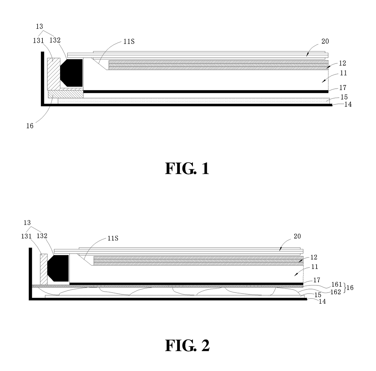
[0020]Referring to FIG. 1, a mobile terminal of the present embodiment includes a backlight module 10 and a display panel 20. The display panel 20 is fixed in an opening of a middle frame 14, and a surface of the display panel 20 may also be covered with a touch screen. The backlight module mainly includes a light guide plate 11, an optical diaphragm group 12 disposed on a light exiting surface of the light guide plate 11, a middle frame 14, a radiating fin 15, a heat conducting connector 16, a backlight source 13 disposed at a light incident end of the light guide plate 11, and a reflective sheet 17 attached on the light guide plate 11 and disposed opposite to the radiating fin 15. The middle frame 14 is disposed on an outer surface of the backlight module and includes a bottom plate and a side wall. The radiating fin 15 is attached to an internal surface of the bottom plate of the middle frame 14, and the heat conducting connector 16 includes a first portion that contacts the back...
embodiment 2
[0024]As illustrated in FIG. 2, different from Embodiment 1, a heat conducting connector 16 of the present embodiment includes a carrying plate 161 and a plurality of spring sheets 162 disposed on a bottom surface of the carrying plate 161. The compressed spring sheets 162 are interposed between the carrying plate 161 and a radiating fin 15, a light guide plate 11 and a backlight source 13 are carried on an upper surface of the carrying plate 161, and the backlight source 13 is attached to one end of the carrying plate 161. The carrying plate 161 may be also used as a flatness holder of the light guide plate 11. The spring sheets 162 are disposed on the carrying plate 161 in an array. When assembling the backlight module 10, a module having metal springs 162 is placed on the radiating fin 15 of a middle frame 14, the compressed springs 162 are nearly completely fitted on the radiating fin 15 to also form a plurality of radiating fins simultaneously, which may improve heat dissipatio...
PUM
 Abstract
Description
Claims
Application Information