Control damping method applied to the resonance inhibition of LLCL single-phase grid connected inverter

A resonance suppression and inverter technology, applied in the field of control damping method for resonance suppression of LLCL single-phase grid-connected inverters, can solve the problem of weakening filter high-frequency harmonic attenuation performance, closed-loop control system instability, and resonance suppression effect Reduce and reduce other problems, achieve the effect of improving filter performance and grid-connected power quality, improving power grid-connected efficiency, and suppressing harmonic current components

Inactive Publication Date: 2014-04-23
开封光利高科实业有限责任公司
View PDF6 Cites 15 Cited by
  • Summary
  • Abstract
  • Description
  • Claims
  • Application Information

AI Technical Summary

Problems solved by technology

However, the LLCL filter belongs to a high-order circuit network, and there is a resonance peak in the mid-frequency band, which is likely to cause instability in the closed-loop control system, so effective resonance suppression measures are required
[0005] The commonly used resonance suppression method at present is the element damping method, that is, the series / parallel resistance elements on the capacitor of the LLCL filter can suppress the resonance. This method does not need to add additional control algorithms and is simple to implement, but the series / parallel resistance elements It needs to consume a large amount of active power, which brings certain challenges to the heat dissipation design of the system. If the resistance value of the resistance element is too large, the loss will be large, which will reduce the power generation efficiency. The large inductance of the grid leads to the reduction of the resonance suppression effect
At the same time, adding resistive elements will weaken the filter's attenuation performance of high-frequency harmonics

Method used


Image

  • Control damping method applied to the resonance inhibition of LLCL single-phase grid connected inverter
  • Control damping method applied to the resonance inhibition of LLCL single-phase grid connected inverter
  • Control damping method applied to the resonance inhibition of LLCL single-phase grid connected inverter

Examples


Embodiment Construction

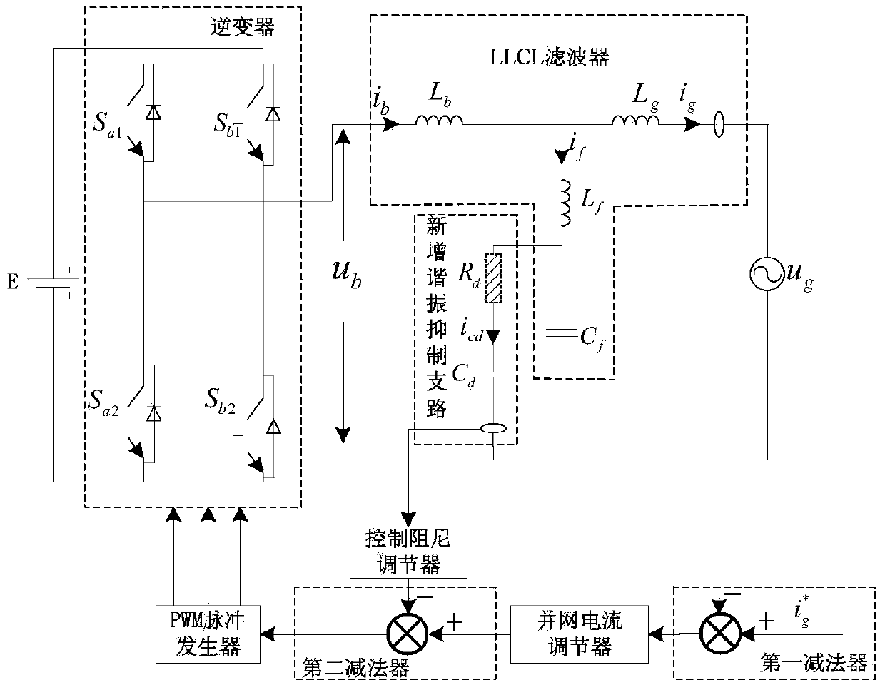
[0027] Description of the symbols and labels involved in the drawings and text:

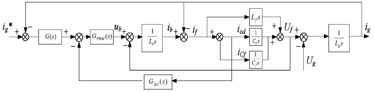
[0028] E—grid-connected inverter DC side voltage; u b - grid-connected inverter output voltage; i b — grid-connected inverter output current; S a1 , S a2 , S b1 , S b2 —power switch tube; L b —Inverter side reactor; L g — grid side reactor; C f — Resonance suppression branch filter capacitor; L f — Resonance suppression branch filter inductance; i f — Flow through the filter inductor L f current; C d — in parallel with the filter capacitor C f Resonance suppression capacitance at both ends; i cd — Flow through the resonance suppression capacitor C d current; R d —Resistive element equivalent to control damping method; u g —grid voltage; i g —grid-connected current; G(s)—transfer function of grid-connected current regulator; G Rd (s)—control damping regulator transfer function; G PWM (s)—PWM pulse generator equivalent transfer function.

[0029] In the prior art, the filter capa...


PUM


Abstract

The invention discloses a control damping method applied to the resonance inhibition of an LLCL single-phase grid connected inverter. The method comprises the steps of connecting resonance inhibition capacitors Cds at two ends of a filter capacitor Cf of an LLCL filter resonance inhibition branch circuit in parallel, and using a current icd flowing by the resonance inhibition capacitors Cds as a feedback control signal, wherein the feedback control signal is added into a control system of the grid connected inverter after being adjusted by a control damping adjuster. According to the control damping method applied to the resonance inhibition of the LLCL single-phase grid connected inverter, the loss and temperature rising problems of an element damping method are effectively solved, the resonance peak of the LLCL filter in the medium frequency band can be effectively inhibited, the filter performance of the LLCL filter is improved, the grid connected waveform and the harmonic content of the grid connected inverter are effectively improved and the grid connected performances of the single-phase grid connected inverter are improved.

Description

technical field [0001] The invention belongs to the technical field of control of grid-connected converters, and in particular relates to a control damping method applied to resonance suppression of LLCL single-phase grid-connected inverters. Background technique [0002] The voltage-type grid-connected inverter has the advantages of low output current harmonic content, power factor adjustment and bidirectional energy flow, small size and light weight, so it is used in grid-connected power generation systems of active filtering, electric drive and solar energy and other renewable energy and other fields have been widely used. [0003] Grid-connected inverters generally use high-frequency PWM modulation technology, which may cause a large amount of high-order harmonic current to be injected into the grid, which will pollute the grid voltage and even seriously affect the operation and work of electrical equipment. The grid-connected current must pass through a filter device to...

Claims


Application Information

Patent Timeline
Patent Type & Authority Applications(China)
IPC IPC(8): H02M7/5383H02M1/12H02J3/38
CPCY02B70/10
Inventor 王喜峰崔坤宋斌王保民张涛赵建军
Owner 开封光利高科实业有限责任公司
Why Eureka
Try Eureka