High power case fuse

a high-power case, fuse technology, applied in the direction of coupling device connection, coupling contact member, coupling device details, etc., can solve the problems of low conductivity, low conductivity of copper alloys and copper alloys, and high mechanical stress properties, so as to achieve high-power fuse and mechanical stress greater

Inactive Publication Date: 2009-09-29
LEAR CORP
View PDF37 Cites 52 Cited by
  • Summary
  • Abstract
  • Description
  • Claims
  • Application Information

AI Technical Summary

Benefits of technology

[0010]The present invention has the advantage of providing a high power fuse assembly that maintains a predetermined normal force on a respective set of female terminals that resists relaxation such that a respective contact area is maintained at elevated temperatures using a separate spring / clamp-like member. The clamp-like member is produced from a material having high mechanical stress properties such as stainless steel. That is, the clamp-like member has greater mechanical stress properties at elevated temperatures in comparison to the material of the female terminals of the fuse. Utilizing a material with good stress relaxation properties at elevated temperatures for the clamp-like member allows for the use of high conductive materials for the female terminals. This assists in maintaining the respective contact area at elevated temperatures and allows more current to be carried through the fuse while maintaining a respective footprint of the fuse assembly within a plastic housing.

Problems solved by technology

Copper which is has good electrical conductivity properties is preferably used to produce the fuse body; however, copper is susceptible to relaxation as temperature increases.
Since the fuse body is encased within the housing, the thickness of the female terminals (i.e., the springs) is limited to a predetermined size due to packaging constraints.
The disadvantage is that the copper alloy has lower conductivity properties in comparison to copper-based material.
As a result, the fuse assembly, given the perspective footprint, are limited to 60 amps or less.

Method used


Image

  • High power case fuse
  • High power case fuse
  • High power case fuse

Examples


Embodiment Construction

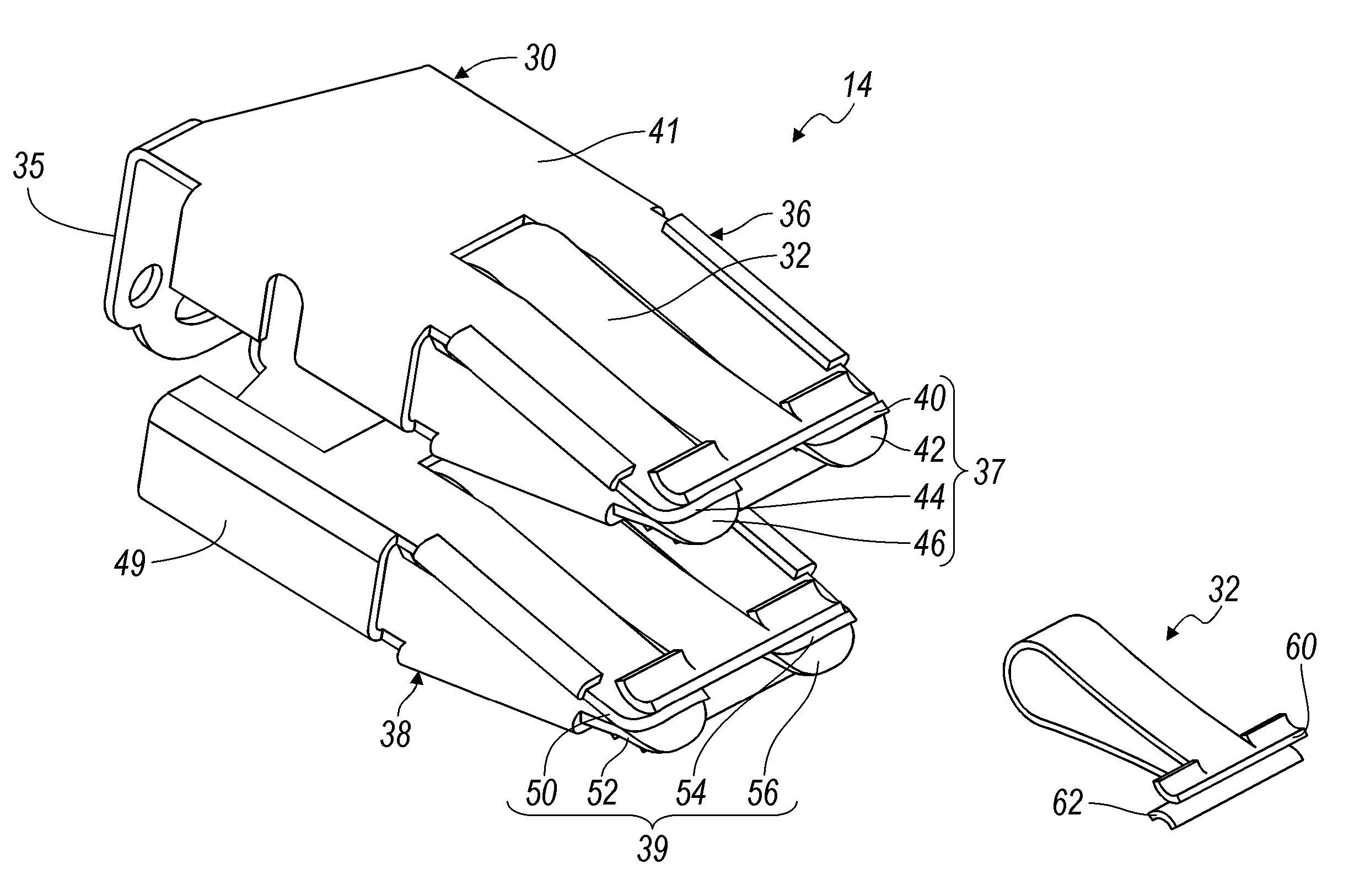
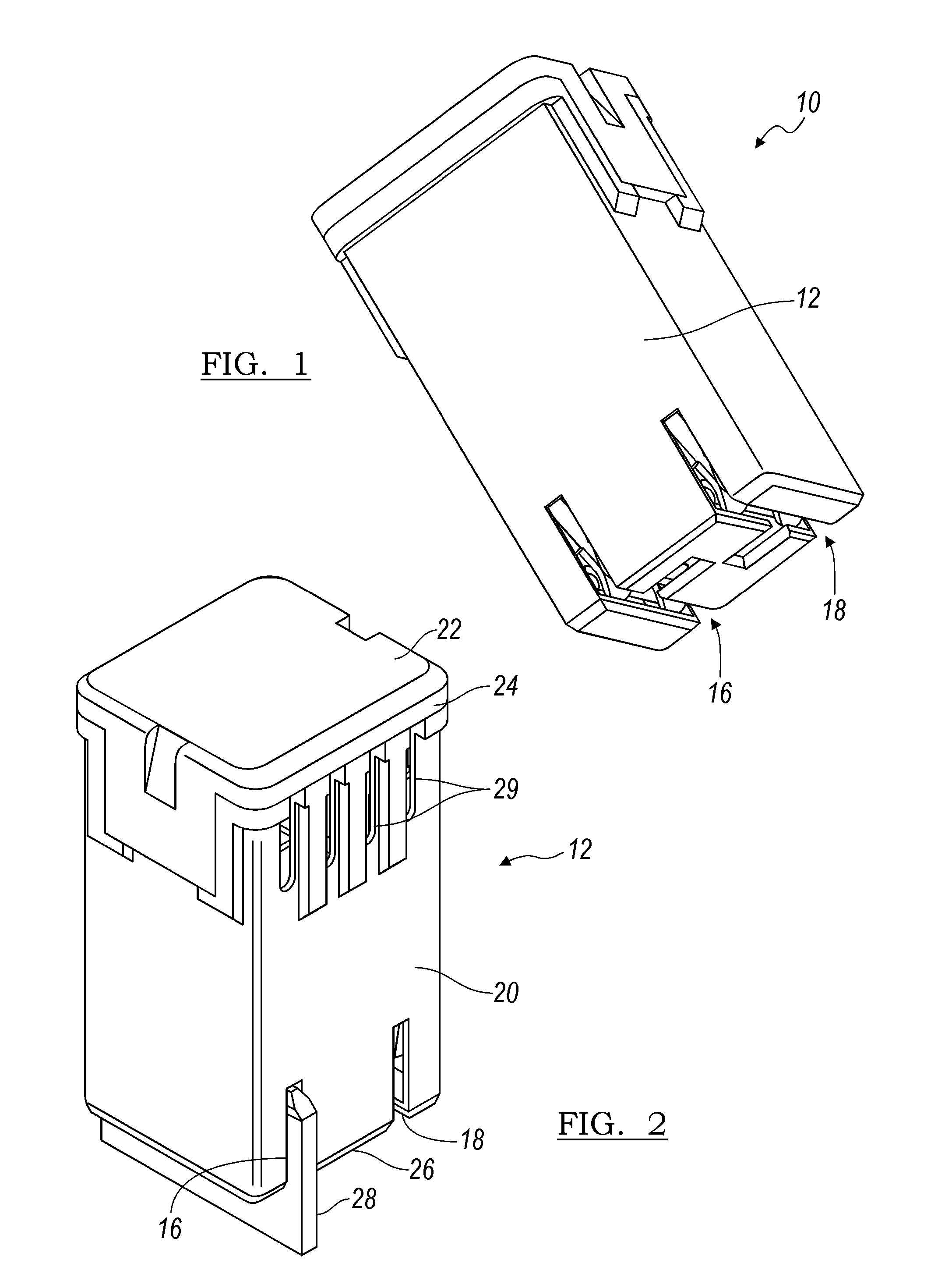
[0021]Referring now to the drawings, there is illustrated in FIG. 1 a high power fuse shown generally at 10. The high power fuse 10 includes a housing 12 and a fuse assembly 14 disposed within the housing 12. The housing 12 includes a first slot 16 for receiving a first terminal blade (not shown) and a second slot 18 for receiving a second terminal blade (not shown).

[0022]FIG. 2 illustrates a perspective view of the housing 12. The housing 12 is preferably produced from two sections that include a body portion 20 and a lid portion 22. The body portion 20 is an elongated chamber that includes an open end 24 and a closed end 26. The open end 24 is of a sufficient width and length for receiving and housing the fuse assembly 14 (shown in FIG. 3) within the housing 12. The first slot 16 and the second slot 18 are formed in the closed end 26. The slots are aligned with respective receiving members for making an electrical connection with a respective terminal blade (shown generally at 28)...


PUM


Abstract

A high power fuse includes a fuse body having a first terminal receptor including a first set of terminal legs and a second terminal receptor in spaced relation to the first terminal receptor. The second terminal receptor includes a second set of terminal legs. A fuse element is disposed between the first terminal receptor and the second terminal receptor. A first clamp-like member is mounted to the fuse body for applying a predetermined compression force against the first set of terminal legs and is configured to secure a first male terminal between the first set of terminal legs. A second clamp-like member is mounted to the fuse body for applying a predetermined compression force against the second set of terminal legs and is configured to secure a second male terminal between the second set of terminal legs.

Description

CROSS-REFERENCE TO RELATED APPLICATIONS[0001]Not ApplicableSTATEMENT REGARDING FEDERALLY SPONSORED RESEARCH OR DEVELOPMENT[0002]Not ApplicableREFERENCE TO A SEQUENCE LISTING, A TABLE, OR A COMPUTER PROGRAM LISTING COMPACT DISC APPENDIX[0003]Not ApplicableBACKGROUND OF THE INVENTION[0004]1. Field of Invention[0005]This invention relates in general to fuses, and in particular to high power case fuses.[0006]2. Background of Related Art[0007]High power distribution box fuse assemblies used in vehicles commonly include a nonconductive housing encasing a conductive set of female terminals (i.e., fuse body). The set of female terminals are joined by a fuse element disposed therebetween. The female terminals are inserted over a set of male blade terminals extending from the power distribution box for completing an electrical circuit. The female terminals are typically designed with a spring-type feature to maintain a strong electrical contact with the male terminal blades. If the current dr...

Claims


Application Information

Patent Timeline
Patent Type & Authority Patents(United States)
IPC IPC(8): H01H85/153H01H85/143
CPCH01H85/0417H01H85/0452H01H85/2035
Inventor PAVLOVIC, SLOBADANZEIDAN, MOHAMADMENZIES, DAVID
Owner LEAR CORP
Why Eureka
Try Eureka