Commom zoom optical system

Inactive Publication Date: 2006-03-30
NIKON CORP
View PDF3 Cites 6 Cited by
  • Summary
  • Abstract
  • Description
  • Claims
  • Application Information

AI Technical Summary

Benefits of technology

[0023] According to the present invention, a common zoom optical system can be provided that is almost commonly used as a component in a pl

Problems solved by technology

However, in order to develop a plurality of zoom lenses for each product series, much burden becomes necessary with respect to R&D manpower, development length and cost for expanding production facilities like production lines.
However, there are drawbacks in that fluctuation in aberrations and dev

Method used


Image

  • Commom zoom optical system
  • Commom zoom optical system
  • Commom zoom optical system

Examples


Example

FIRST EXAMPLE

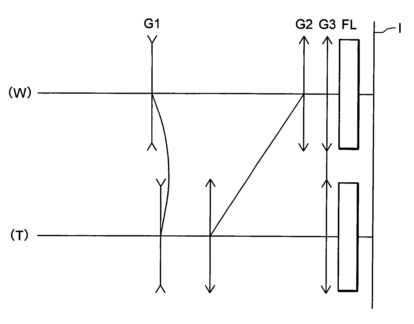
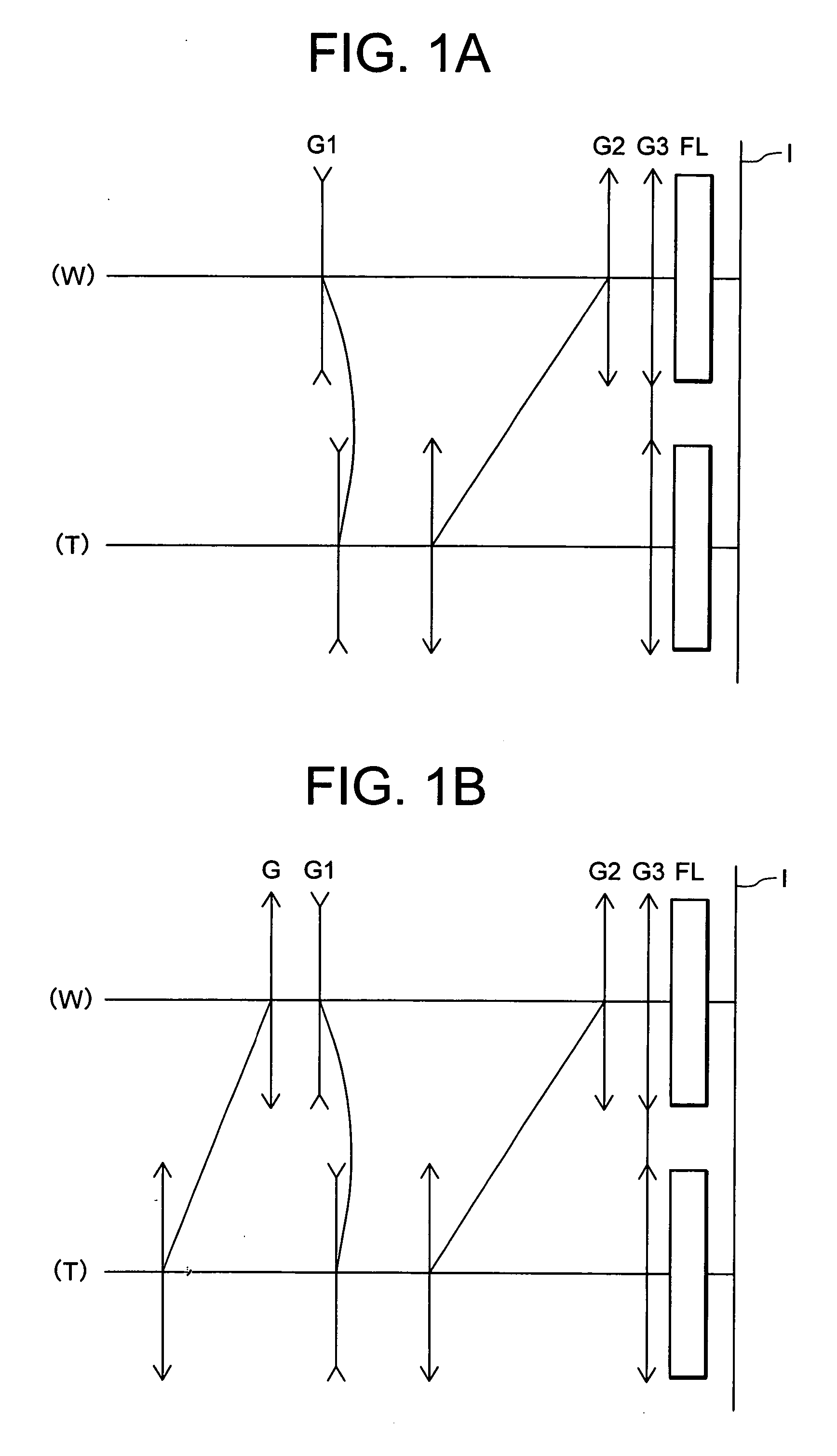
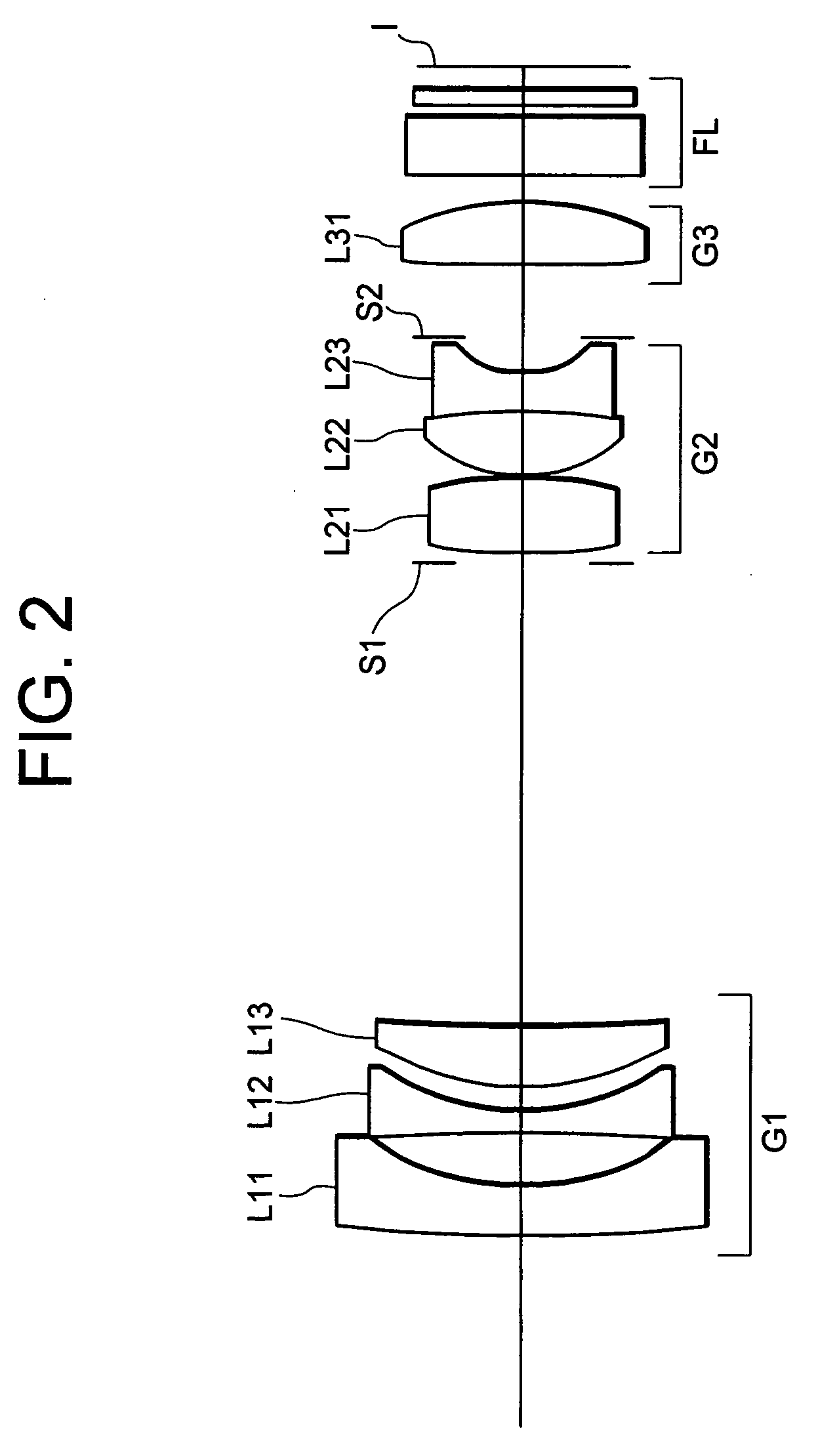
[0096]FIGS. 2 and 3 are views showing configurations of zoom lenses A and B composed by use of a common zoom optical system according to a first example of a preferred embodiment of the present invention.

[0097] In the zoom lens A shown in FIG. 2, a first lens group G1 includes, in order from an object side, a negative meniscus lens L11 with a convex surface facing to an object side, a double concave negative lens L12 and a positive meniscus lens L13 with a convex surface facing to an object side.

[0098] A second lens group G2 includes, in order from an object side, an aperture stop S1, a double convex positive lens L21, a negative cemented lens constructed by a double convex positive lens L22 and a double concave negative lens L23 and a flare stop S2.

[0099] A third lens group G3 is composed of a double convex positive lens element L31.

[0100] A filter group FL includes a low pass filter, an infrared cut filter or the like.

[0101] An image plane I is formed on an imag...

Example

SECOND EXAMPLE

[0118]FIGS. 10 and 11 are diagrams showing lens constructions of zoom lenses A an B composed by use of the common zoom optical system according to the second example of the preferred embodiment of the present invention.

[0119] In zoom lens A shown in FIG. 10, a first lens group G1 includes, in order from an object side, a negative meniscus lens L11 with a convex surface facing to the object side, a double concave negative lens L12, and a double convex positive lens L13.

[0120] A second lens group G2 includes, in order from the object side, an aperture stop S1, a double convex positive lens L21, a negative cemented lens consisting of a double convex positive lens L22 and a double concave negative lens L23, and a flare stop S2.

[0121] A third lens group G3 is composed of a single positive meniscus lens element L31 with a convex surface facing to an image.

[0122] A filter group FL includes a filter such as a low pass filter, an infrared cut filter, or the like.

[0123] Th...


PUM


Abstract

The common zoom optical system is provided that is almost commonly used in a plurality of zoom lenses as a component and that is capable of suppressing fluctuation in aberrations and deviation in the position of the image plane, wherein the common zoom optical system is almost commonly used in a plurality of zoom lenses as a component, and when zooming from a wide-angle end state of a plurality of the zoom lenses composed by use of the common zoom optical system to a telephoto end state thereof, a moving path of the common zoom optical system differs for each zoom lens.

Description

[0001] This application claims the benefit of Japanese Patent applications No. 2004-289038 and No. 2005-273259 which are hereby incorporated by reference. BACKGROUND OF THE INVENTION [0002] 1. Field of the Invention [0003] The present invention relates to a common zoom optical system almost commonly used as a component in a plurality of zoom lenses suitable for a video camera, digital still camera and the like using a solid-state image pick-up device and the like. [0004] 2. Related Background Art [0005] Generally, a zoom lens has a merit in that a user can take a photograph with high degree of freedom while choosing a focal length at random (a state of a focal length of a lens being the shortest is a wide-angle end state and a state of a focal length of a lens being the longest is a telephoto end state.) Thus, in recent years, the zoom lens has been typically mounted on a camera photographing a subject using the solid-state image pick-up device such as CCD, MOS, etc., for example, t...

Claims


Application Information

Patent Timeline
IPC IPC(8): G02B15/14
CPCG02B15/177G02B15/143507
Inventor TAKE, TOSHINORIARAI, DAISAKU
Owner NIKON CORP
Why Eureka
Try Eureka