Hall element

Active Publication Date: 2018-09-27
ASAHI KASEI ELECTRONICS CO LTD
View PDF8 Cites 1 Cited by
  • Summary
  • Abstract
  • Description
  • Claims
  • Application Information

AI Technical Summary

Benefits of technology

[0008]According to an aspect of the invention, a fluctuation in stress accompanied by a change in temperature environment, and the like is suppressed by a ball portion

Problems solved by technology

For this reason, when a deformation and the like occur in a mold resin covering the circumference of the body of the hall element due to changes in a temperature environment,

Method used


Image

  • Hall element
  • Hall element
  • Hall element

Examples


Example

[0022]In the following detailed description, many specific concrete configurations are described so as to provide the complete understanding of an embodiment of the invention. However, it is apparent that the invention is not limited to such specific concrete configurations, and other embodiments can be implemented. In addition, the following embodiment does not limit the invention according to claims, and includes all combinations of characteristic configurations described in the embodiment.

[0023]Hereinafter, an embodiment of the invention will be described with reference to the accompanying drawings. In the following description of the drawings, the same portions are denoted by the same reference numerals and signs. However, the drawings are schematic drawings, and a relationship between a thickness and a planar dimension, a thickness ratio in layers, and the like are different from those in real life.

Embodiment

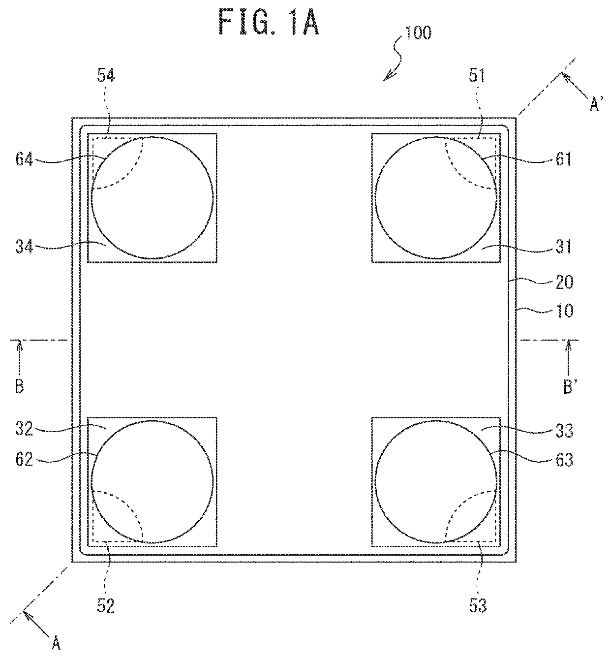
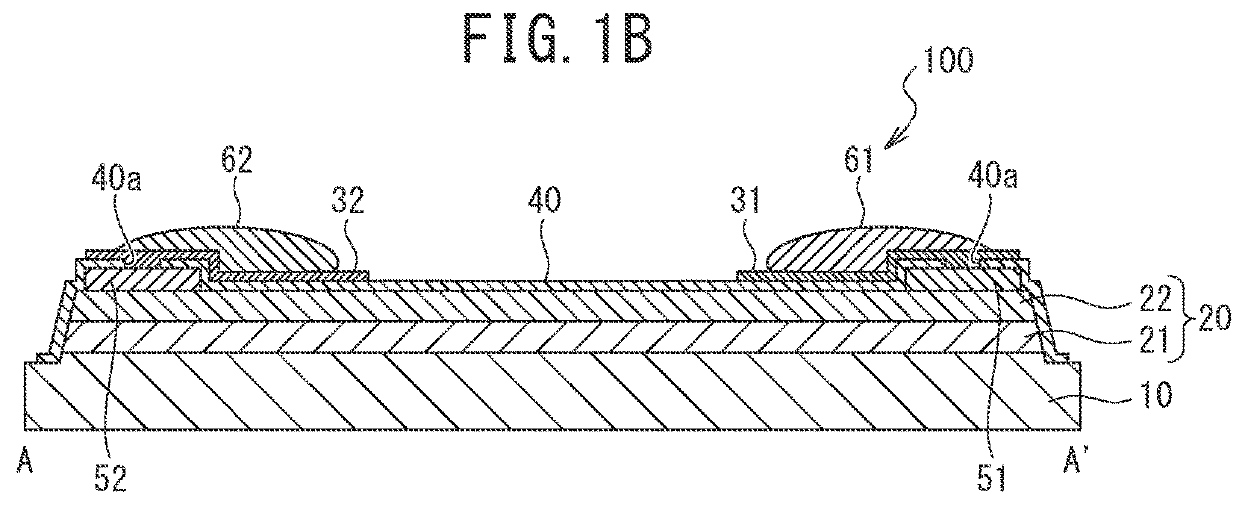
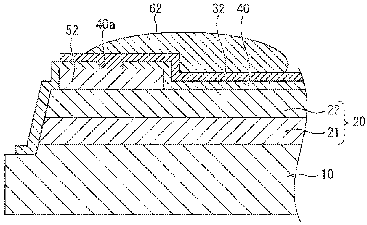
[0024]FIG. 1A is a top view illustrating an example of a hall element ...


PUM


Abstract

A hall element is provided to suppress fluctuation in a Hall output voltage of the hall element which is generated due to a fluctuation in stress. The hall element may be formed to include a substrate, a magnetosensitive portion formed on the substrate, an insulating film formed on the magnetosensitive portion, four conductive portions (electrode portions and contact portions) which are formed on the insulating film, electrically connected to the magnetosensitive portion through the insulating film, and disposed at positions serving as vertexes of a quadrangle, and ball portions electrically connected to the conductive portions, and at least one ball portion is disposed on a diagonal line of the quadrangle formed by a region surrounded by the four conductive portions and above a portion where the conductive portion and the insulating film are in contact with each other.

Description

BACKGROUND OF THE INVENTIONField of the Invention[0001]The present invention relates to a hall element.Description of the Related Art[0002]In recent years, a hall element including a contact for connecting a magnetosensitive portion and an electrode pad to each other has been known (see for example, PTL 1 and PTL 2).CITATION LISTPatent Literature[0003]PTL 1: JP 60-175471 A[0004]PTL 2: JP 62-12974 ASUMMARY OF THE INVENTION[0005]In a hall element of the related art, a current is concentrated on a lower end of a contact. For this reason, when a deformation and the like occur in a mold resin covering the circumference of the body of the hall element due to changes in a temperature environment, and the like, a fluctuation in stress occurs in the body of the hall element due to the deformation, and thus there is a possibility that a local change in conductivity occurs. Particularly, in a case where a fluctuation in stress occurs in the vicinity of the circumference of the contact on which...

Claims


Application Information

Patent Timeline
IPC IPC(8): H01L43/04H01L43/14
CPCH01L43/04H01L43/14H01L43/10H01L43/065G01R33/07H01L2224/48091H01L2924/181H01L2224/48247H01L2924/18165H10N52/80H10N52/101H10N52/01H01L2924/00014H01L2924/00012H01L23/04H10B61/00H10N59/00H10N50/85
Inventor SHOJI, TOMOYAAKAGI, TSUYOSHI
Owner ASAHI KASEI ELECTRONICS CO LTD
Why Eureka
Try Eureka