Motor driver

Inactive Publication Date: 2019-06-20
DENSO CORP
View PDF13 Cites 0 Cited by
  • Summary
  • Abstract
  • Description
  • Claims
  • Application Information

AI Technical Summary

Benefits of technology

[0005]The present disclosure describes a motor driver capable of suppressing a fluctuation in an electric current flowing t

Problems solved by technology

The switching of the switching elements may cause an increase in current fluctuations flowing thr

Method used


Image

  • Motor driver
  • Motor driver
  • Motor driver

Examples


Example

First Embodiment

[0020]The first embodiment of the present disclosure is described with reference to FIGS. 1 to 6.

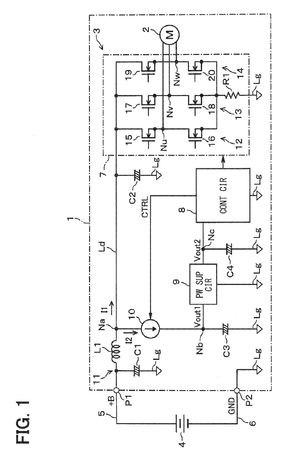
[0021]With reference to FIG. 1, a motor-inverter 1 may include a motor 2 and a motor driver 3. The motor 2 may be disposed in a vehicle (not shown). The motor 2 may be, for example, an electric motor of an engine cooling fan, radiator cooling fan, or other cooling fan. The motor driver 3 receives a power supply to drive the motor 2 from a direct current (DC) power source 4 via a pair of DC power supply lines 5 and 6. The DC power source 4 may be, for example, an in-vehicle battery that supplies electric power to the motor driver 3 via the terminals P1 and P2. The terminal P2 may be connected to a ground line Lg or like return path to provide a reference potential (e.g., 0 V) at a position inside the motor-inverter 1.

[0022]The motor driver 3 includes capacitors C1, C2, C3, and C4, an inductor L1, an inverter main circuit 7, a control circuit 8, a power supply circuit 9, an...

Example

Second Embodiment

[0078]The second embodiment of the present disclosure is described with reference to FIGS. 7 and 8. As shown in FIG. 7, the motor driver 42 of the motor-inverter 41 in the present embodiment is different from the motor driver 3 of the first embodiment in that the motor-inverter 41 includes a control circuit 43 in place of the control circuit 8, and includes a current adjuster circuit 44 in place of the current adjuster circuit 10.

[0079]The control circuit 43 monitors the voltage Vout1 of the node Nb. The configuration and the components of the control circuit 43 may be similar to the configuration and the components of the control circuit 8. For example, the control circuit 43 may include all the same components as the control circuit 8 shown in FIG. 5 with the addition of an additional input for monitoring the voltage Vout1 at the node Nb. As such, like components in the control circuit 43 use the same reference characters as those in the control circuit 8 and are ...

Example

Third Embodiment

[0093]The third embodiment of the present disclosure is described with reference to FIGS. 9 and 10. As shown in FIG. 9, a motor driver 52 of a motor-inverter 51 in the present embodiment is different from the motor driver 3 in the first embodiment in that the motor driver 52 includes a control circuit 53 in place of the control circuit 8, includes a current adjuster circuit 54 in place of the current adjuster circuit 10, and includes a power supply circuit 55 in place of the power supply circuit 9.

[0094]The control circuit 53 monitors the voltage Vout1 of the node Nb. The configuration and the components of the control circuit 53 may be similar to the configuration and the components of the control circuit 8. For example, the control circuit 53 may include all the same components as the control circuit 8 shown in FIG. 5 with the addition of an additional input for monitoring the voltage Vout1 at the node Nb. As such, like components in the control circuit 53 use the ...


PUM


Abstract

A motor driver drives a motor by receiving a power supply from a direct current power source, and includes a half-bridge circuit, a smoothing capacitor, a power supply circuit, a current adjuster circuit, and a control circuit. The half-bridge circuit and the smoothing capacitor are connected at positions between a power supply line and a ground line. The current adjuster circuit adjusts a current supply amount to the power supply circuit. The control circuit controls the half-bridge circuit and the current adjuster circuit. The control circuit controls the current adjuster circuit based on an operating state of the half-bridge circuit.

Description

CROSS REFERENCE TO RELATED APPLICATION[0001]The present application is based on and claims the benefit of priority of Japanese Patent Application No. 2017-239528, filed on Dec. 14, 2017, the disclosure of which is incorporated herein by reference.TECHNICAL FIELD[0002]The present invention generally relates to a motor drive device, or a motor driver, that receives a power supply from a direct current (DC) power source through a pair of DC power supply lines and drives a motor.BACKGROUND INFORMATION[0003]A motor driver may be used to drive a motor mounted on a vehicle by receiving a power supply from a direct current (DC) power source such as a battery via a pair of DC power supply lines. Such a motor driver may have a half-bridge circuit composed of two switching elements connected in series at a position between the DC power supply lines, and may be configured to adjust a winding current of the motor by switching the drive of these switching elements.[0004]The switching of the switc...

Claims


Application Information

Patent Timeline
IPC IPC(8): H02P6/10H02M3/158H02M7/5387H02M1/14
CPCH02P6/10H02M3/1582H02M7/5387H02M1/14H02P2201/07H02M2001/0009H02M3/158H02M7/53875H02M1/0009
Inventor IMURA, TAKASHI
Owner DENSO CORP
Why Eureka
Try Eureka