

Imaging lens and imaging apparatus
- Summary
- Abstract
- Description
- Claims
- Application Information
AI Technical Summary
Benefits of technology
Problems solved by technology
Method used
Image

Examples
Embodiment Construction
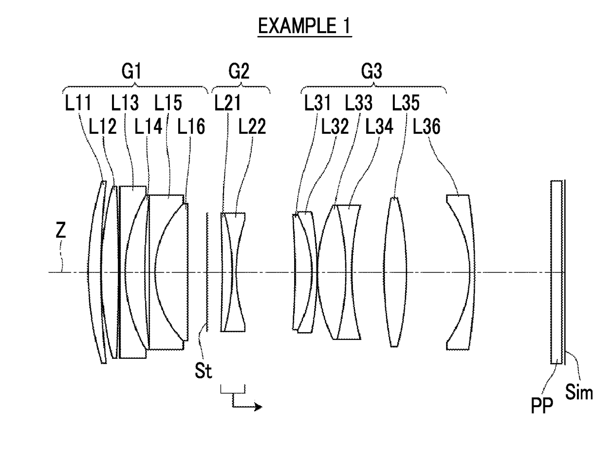
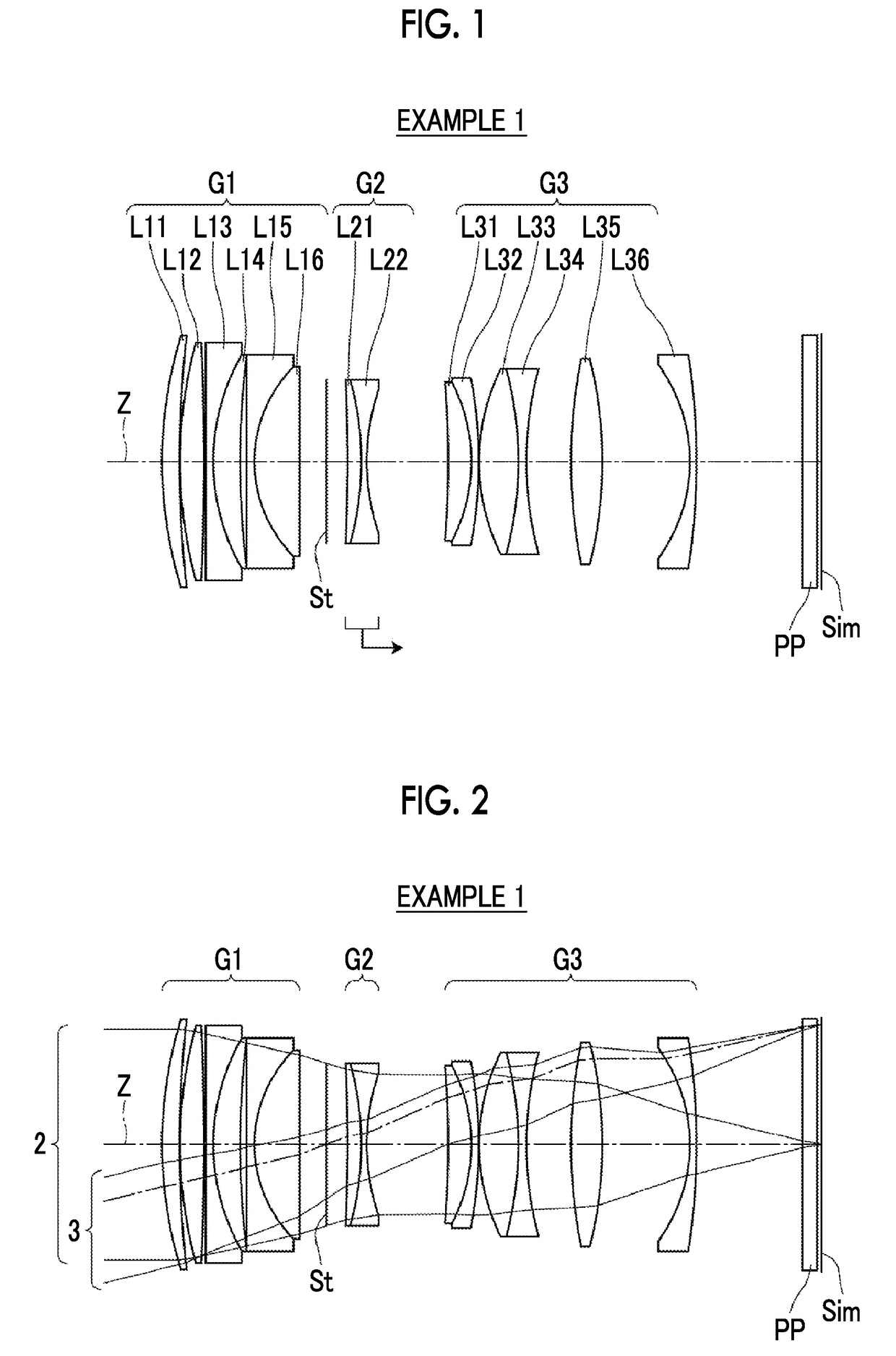
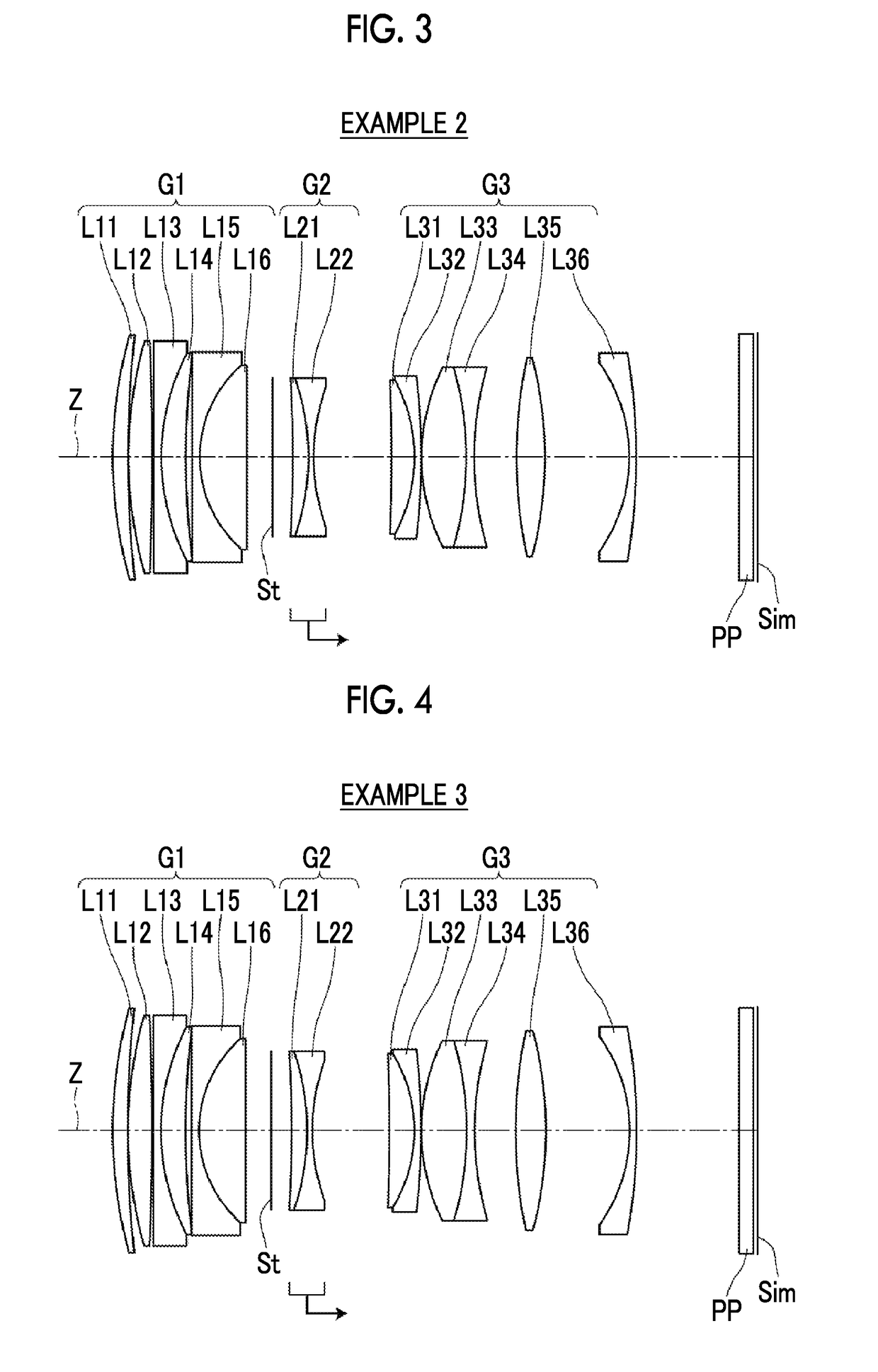
[0079]Hereinafter, embodiments of the present invention will be described with reference to drawings. FIG. 1 is a cross-sectional view illustrating a lens configuration of an imaging lens (common to Example 1) according to an embodiment of the present invention. The exemplary configuration shown in FIG. 1 is the same as the configuration of the imaging lens of Example 1 to be described later. In FIG. 1, the left side is the object side, and the right side is the image side. Further, FIG. 2 shows an optical path diagram of an imaging lens according to an embodiment shown in FIG. 1, and shows optical paths of on-axis rays 2 and rays with the maximum angle of view 3 from the object point at the infinite distance. FIGS. 1 and 2 and FIGS. 3 to 11 to be described later show lens configurations in a state where the object at infinity is in focus.
[0080]As shown in FIGS. 1 and 2, the imaging lens of the present embodiment includes, in order from the object side along an optical axis Z, a fir...
PUM
 Abstract
Description
Claims
Application Information