
Lighting apparatus for a museum display case

a technology for museum display cases and light fixtures, which is applied in the direction of lighting and heating equipment, lighting support devices, instruments, etc., can solve the problems of inability to illuminate individual objects within the display cases or enhance, and the value of public display is easily damaged, so as to minimize damage to artifacts, easy to damage, and easy to enhance

Inactive Publication Date: 2006-03-30
LUXAM
View PDF22 Cites 29 Cited by
  • Summary
  • Abstract
  • Description
  • Claims
  • Application Information

AI Technical Summary

Benefits of technology

"The invention provides a support grid for fiber optic lighting fixtures in a display case. The support grid includes longitudinal and transverse support rods that are made of metal or clamped together with coupling devices. The support grid can be formed as a rectangular frame. The invention also provides a lighting apparatus with the support grid, a light source, and a fiber optic bundle. The fiber optic bundle includes a plurality of tails that project light from the end of each tail. The invention also provides a display cabinet with a light chamber, fiber optic bundle, and display chamber that holds the support grid and fixtures. The technical effects of the invention include improved support and stability of fiber optic lighting fixtures, as well as improved lighting and display effects."

Problems solved by technology

Museums typically need to place a number of artifacts that are valuable and easily damaged on public display.
Disadvantages of a reliance on the use of lighting outside the display case to illuminate objects inside the display case include the dominance of reflections on the glass surfaces of the case, an inability to illuminate individual objects within the display case or to enhance the display of individual objects through consideration of the dimensions, shapes, material or the conditions under which they are displayed, and difficulties in changing the illumination in an appropriate way when the objects within the case are changed.
Furthermore, the frequencies of light striking the objects within the display are limited to the frequencies transmitted by the optical fibers and by additional filtration, if desired.

Method used


Image

  • Lighting apparatus for a museum display case
  • Lighting apparatus for a museum display case
  • Lighting apparatus for a museum display case

Examples


Embodiment Construction

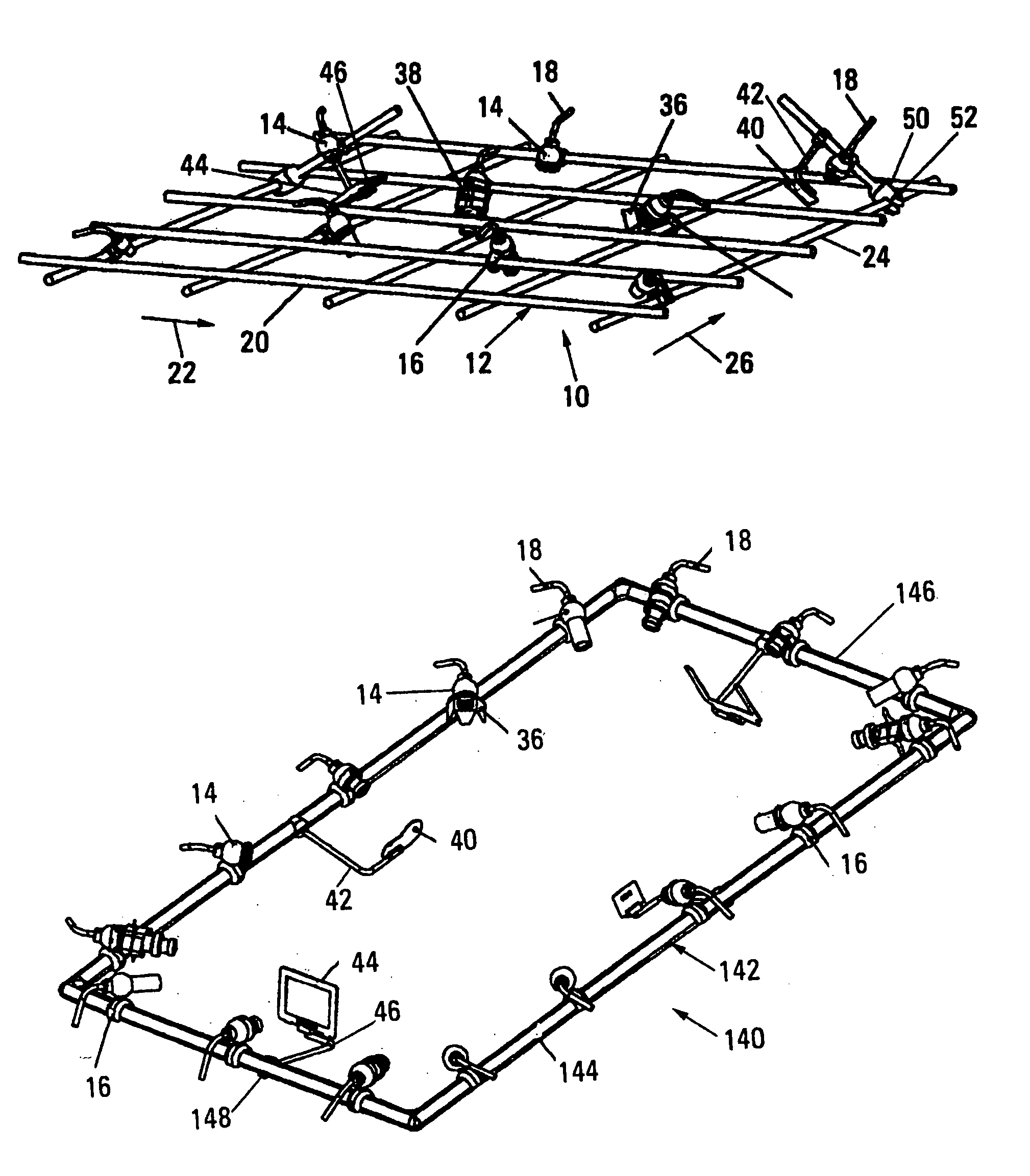
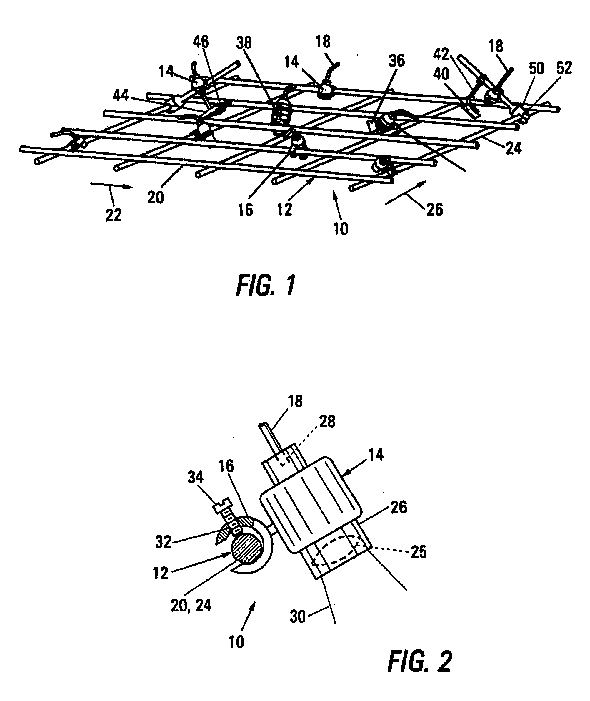
[0027]FIG. 1 is a perspective view of lighting apparatus 10 built in accordance with the present invention to include a support grid 12, to which a number of fiber optic fixtures 14 are attached by means of individual clamps 16. Each of the fixtures 14 is connected to an end of a fiber optic tail 18 through which light is provided to the fixture 14. The support grid 12 includes a number of longitudinal rods 20, extending in the longitudinal direction indicated by arrow 22, along the length of the support grid 12, and a number of transverse rods 24, extending in the transverse direction indicated by arrow 26, across the width of the support grid 12.

[0028]FIG. 2 is a partly sectional elevation of the lighting apparatus 10, showing the attachment of a fixture 14 to one of the rods 20 or 24 of the support grid 12. For example, each of the individual fixtures 14 includes one or more lenses 25 within a tubular housing 26, with the lens(es) 24 being configured to produce, from the light e...


PUM


Abstract

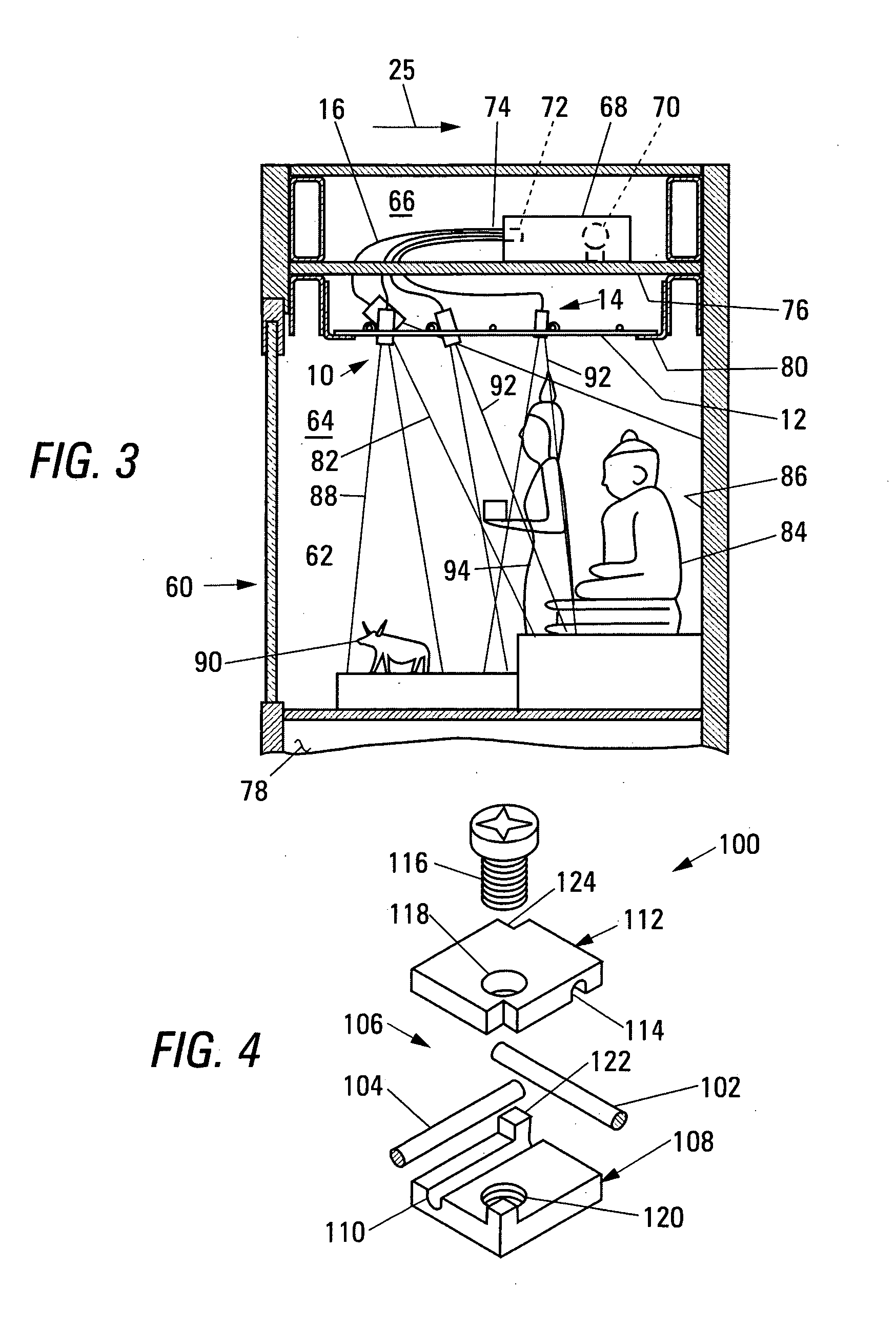
A support grid, formed as a grid including a number of longitudinal support rods and a number of transverse support rods, is used to support a number of lighting fixtures, each of which projects light emitted from an end of a fiber optic tail. The fiber optic tails are joined into a fiber optic bundle illuminated by a light source. The support grid allows placement of the fixtures to be located in the longitudinal and transverse directions to light various objects within chamber of a museum display case, while the light source is held outside the chamber.

Description

BACKGROUND OF THE INVENTION [0001] 1. Field of the Invention [0002] This invention relates to illuminating objects within a display case, and, more particularly, to providing illumination for viewing valuable and easily damaged objects within a museum display case in a manner providing flexibility to establish and modify complex patterns of illumination. [0003] 2. Summary of the Background Art [0004] Museums typically need to place a number of artifacts that are valuable and easily damaged on public display. Such artifacts include archeological treasures, ancient manuscripts, and the like, which include materials and pigments that are easily damaged by exposure to air, moisture, heat, certain forms of energy, such as UV (ultraviolet) energy, and various pollutants. Efforts to protect such artifacts while providing for their display have been centered on the development of air tight display cases with transparent windows, and with appropriate means for conditioning and maintaining th...

Claims


Application Information

Patent Timeline
Patent Type & Authority Applications(United States)
IPC IPC(8): E04H15/10
CPCA47F3/001F21S2/00G02B6/001F21V21/34G02B6/0008F21V21/088
Inventor HOCQUARD, JEAN FRANCOISJELLOW, RICHARD MCDONALDDESVALLEES, ERICSAUVAGE, BRUNO
Owner LUXAM
Learn More