Band averaging circuit and related method for carrier frequency offset estimation in a multi-band multi-carrier communication system

a communication system and carrier frequency offset technology, applied in the field of band averaging circuits, can solve the problems of small difference between original data and demodulated data, and the accuracy of the average carrier frequency offset ratio sub>avg/sub>will be affected seriously by the mistake accordingly, so as to improve the accuracy of carrier frequency offsets, improve the quality of received signals, and efficiently reduce inter carrier interferences.

Active Publication Date: 2006-03-30
REALTEK SEMICON CORP
View PDF5 Cites 12 Cited by
  • Summary
  • Abstract
  • Description
  • Claims
  • Application Information

AI Technical Summary

Benefits of technology

[0012] In summary, the band averaging circuit according to the claimed invention performs a weighted averaging operation on the first, the second and the third carrier frequency offset ratios using a frequency offset adjustment circuit according to the comparison results of the three carrier frequency offset ratios, and further determines the carrier frequency offsets of the first, the second and the third carriers. In this way, the accuracy of the carrier frequency offsets can be improved. Therefore, the carrier frequency offsets generated using the method according to the claimed invention can be utilized for compensating the local oscillating signal to efficiently decrease inter carrier interferences (ICI) in the multi-band multi-carrier communication system. That is, the band averaging circuit and the related method according to the claimed invention are capable of improving the quality of the received signal.

Problems solved by technology

However, practically, even two identical oscillators cannot generate oscillating signals of completely the same frequency and therefore there is a slight difference between the original data and the demodulated data.
However, when estimating any of the first, the second and the third carrier frequency offset ratios, if a serious mistake occurs, the accuracy of the average carrier frequency offset ratio γavg will be affected seriously by the mistake accordingly.

Method used


Image

  • Band averaging circuit and related method for carrier frequency offset estimation in a multi-band multi-carrier communication system
  • Band averaging circuit and related method for carrier frequency offset estimation in a multi-band multi-carrier communication system
  • Band averaging circuit and related method for carrier frequency offset estimation in a multi-band multi-carrier communication system

Examples


Embodiment Construction

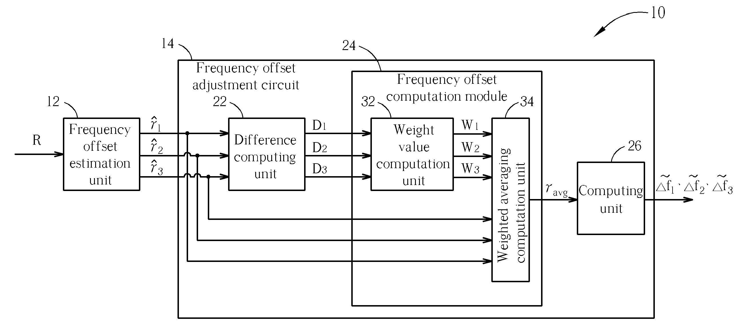
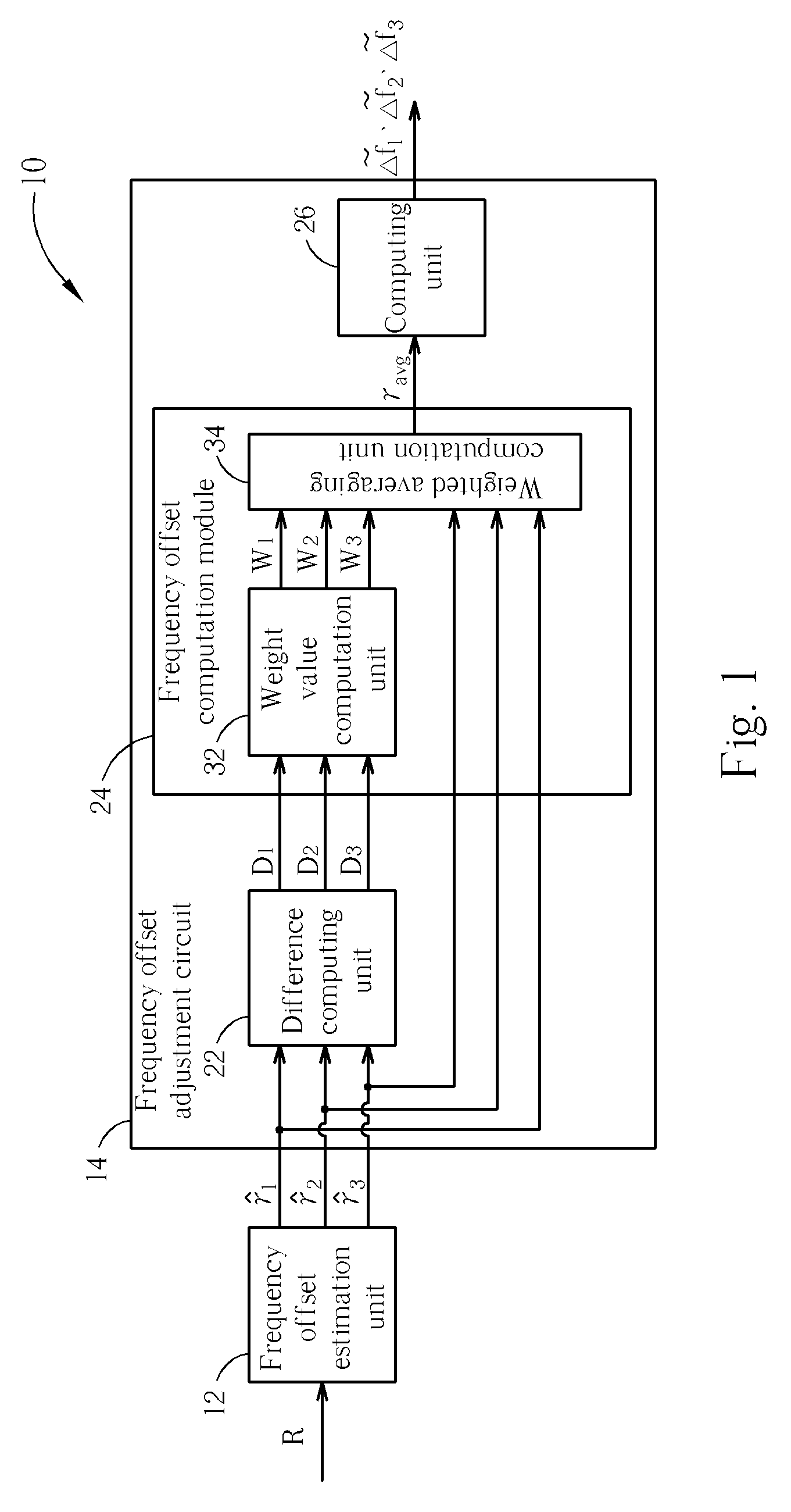
[0016] Please refer to FIG. 1. FIG. 1 is a functional block diagram of a band averaging circuit 10 according to an embodiment of the present invention. The band averaging circuit 10 is utilized for estimating a carrier frequency offset in a multi-band multi-carrier communication system. As shown in FIG. 1, the band averaging circuit 10 comprises a frequency offset estimation unit 12 and a frequency offset adjustment circuit 14. The frequency offset estimation unit 12 is utilized for generating a plurality of carrier frequency offset ratios, such as a first carrier frequency offset ratio {circumflex over (γ)}1, a second carrier frequency offset ratio {circumflex over (γ)}2 and a third carrier frequency offset ratio {circumflex over (γ)}3 in the present embodiment according to a received packet R. Operations and functions of the frequency offset estimation unit 12 are well known to those of ordinary skill in the art and will not be depicted repeatedly. Next, the frequency offset adjus...


PUM


Abstract

A band averaging circuit and a related method for estimating a carrier frequency offset are applied in a multi-band multi-carrier communication system. A packet of the multi-band multi-carrier communication system is transmitted via a plurality of carriers. The band averaging circuit includes a frequency offset estimation unit for generating a plurality of carrier frequency offset ratios corresponding to the carriers according to a received packet; and a frequency offset adjustment circuit coupled to the frequency offset estimation unit for calculating a weighted average carrier frequency offset ratio according to carrier frequency offset ratios and comparison results of the carrier frequency offset ratios, and also for calculating a carrier frequency offset of each carrier according to the weighted average carrier frequency offset ratio and a center frequency of the carrier.

Description

BACKGROUND OF THE INVENTION [0001] 1. Field of the Invention [0002] The present invention relates to a circuit and a method for estimating a carrier frequency offset, and more specifically, to a band averaging circuit and a related method for estimating a carrier frequency offset in a multi-band and multi-carrier communication system. [0003] 2. Description of the Prior Art [0004] In general, data to be transmitted is modulated by a carrier in a communication system to ensure the communication quality of a transmitter and a receiver. In the communication system, the data is modulated by the carrier of a specific frequency at the transmitter utilizing a local oscillator, the modulated data is transmitted through a channel, and the modulated data is received by the receiver. The receiver must utilize a local oscillator to demodulate the received data before reading. However, practically, even two identical oscillators cannot generate oscillating signals of completely the same frequency...

Claims


Application Information

Patent Timeline
Patent Type & Authority Applications(United States)
IPC IPC(8): H03D3/00
CPCH04L2027/0026H04L27/2657
Inventor WU, KUO-MINGLIU, DER-ZHENG
Owner REALTEK SEMICON CORP
Why Eureka
Try Eureka